Select Page
Ski pole

Ski pole

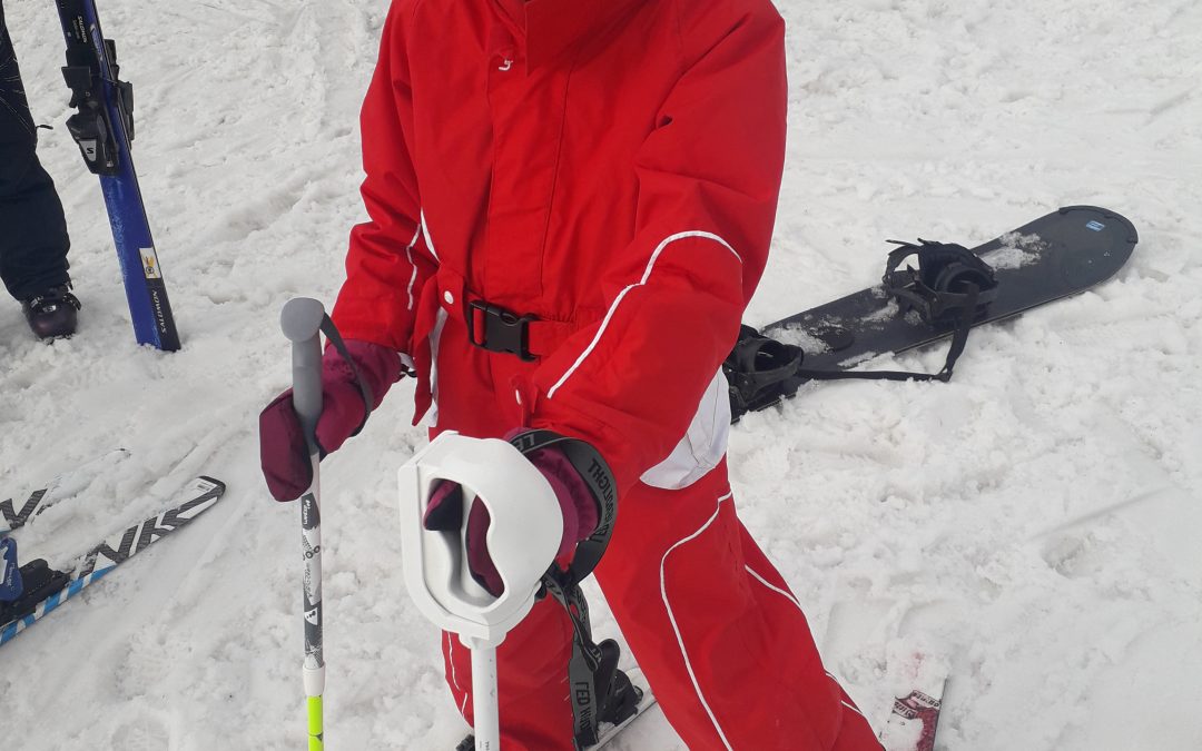
Manon, hope for the 2030 Olympics ?

Our previous design of the ski pole aimed at Pierre-Luc, based on the principle of ball joint that enclosed his palm, does not seem appropriate to us in Manon’s case, because her clamp function can be performed by his thumb and his pinky. Of course the strength of this clamp is clearly not sufficient to hold a ski pole, so we keep the principle of using a socket build around her hand.

We therefore define new specifications intending the left hand palm to have the same feelings of touch as her right hand.

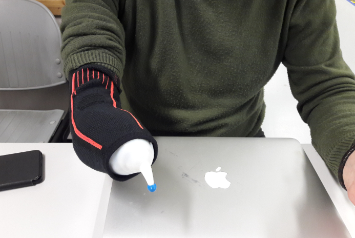
Scan of the left hand, equipped with a muffle

Pour ce nouveau projet, nous essayons de nous passer de l’étape moulage, en réalisant un scan de la main in-situ, en position de maintien du bâton de ski. La main étant équipée d’une moufle qui sera ensuite bien adaptée par la couturière de la famille.

For this new project, we are trying to work without the molding stage, by performing an in-situ live hand scan, right in the position of holding the ski pole. The hand being equipped with a muffle which will then be well adapted by her family’s seamstress (grand’ma).

The scanning operation is not as easy as expected, but after 3 attempts we got a good quality mesh file.
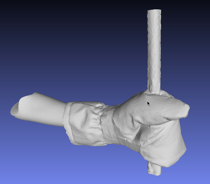
 

Another evolution of our process, we will not transform the resulting mesh (STL format) into a B-rep file for importing into our usual CAD software (Onshape).

Once the STL is imported into an ONshape’s “part studio”, an enveloping surface is made around the mesh, made of multiple ‘Spline’ curves (generalization of Bezier curves) drawn over successive cut planes. These curves, building a group of sections, each of them wrapping the glove, are then connected (joined) to each other by ‘lofts’. A loft is a surface obtained by interpolation between the different curves, in the form of a NURBS surface (cf wikipedia).
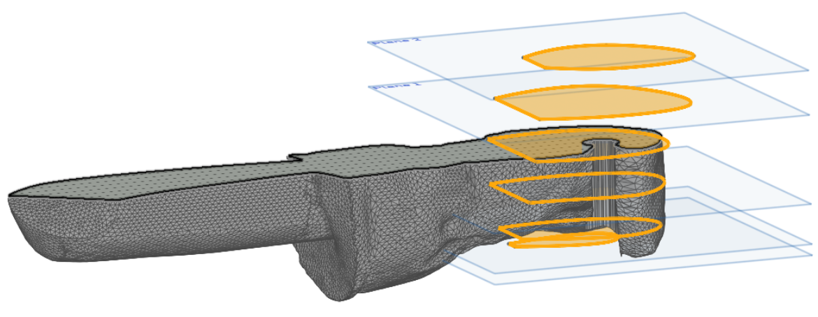
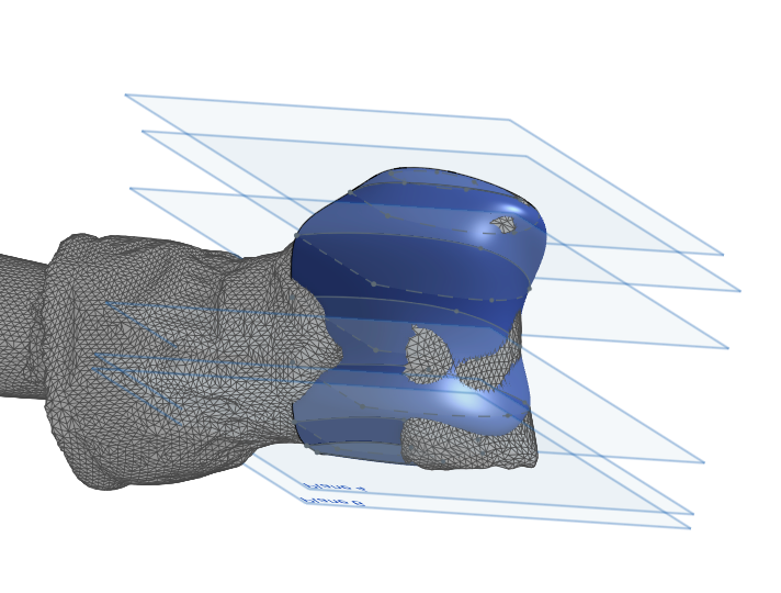
 

A pile of parallel planes will slice the fist holding the pole. All plans are referenced on remarkable points of the muffle.
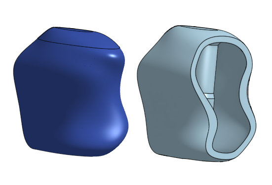
On each plane, a closed curve is drawn to surround all boundaries of the displayed STL, thus creating a section. By interconnecting the successive parallel sections by lofts (3D loft function), we obtain the blue envelope (as a surface) which will then be transformed into volume using the “thicken” function.
After having created thickness to the developed surface, having cut the end of the socket to allow the thumb to come out of it, the socket is ready for integration into the new holding system.

Highlights of the device including a (simple) system.

The new device is therefore no longer based on the ball joint principle but on a two-element system :

  • an element on the stick (host)
  • a detachable socket for Manon’s hand.

The cohesion of the two elements is achieved by neodymium magnets, powerful enough for the stick to follow each hand’s movements, but detachable enough to allow the release of the socket in case of fall.
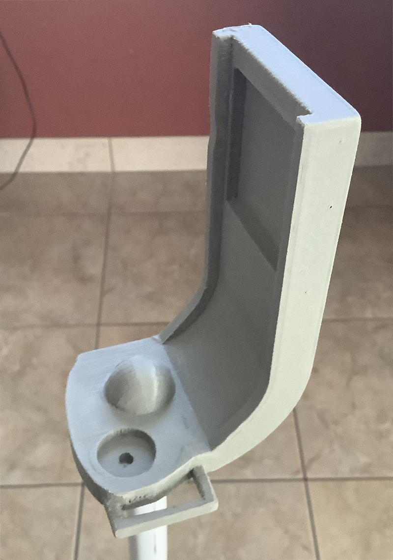
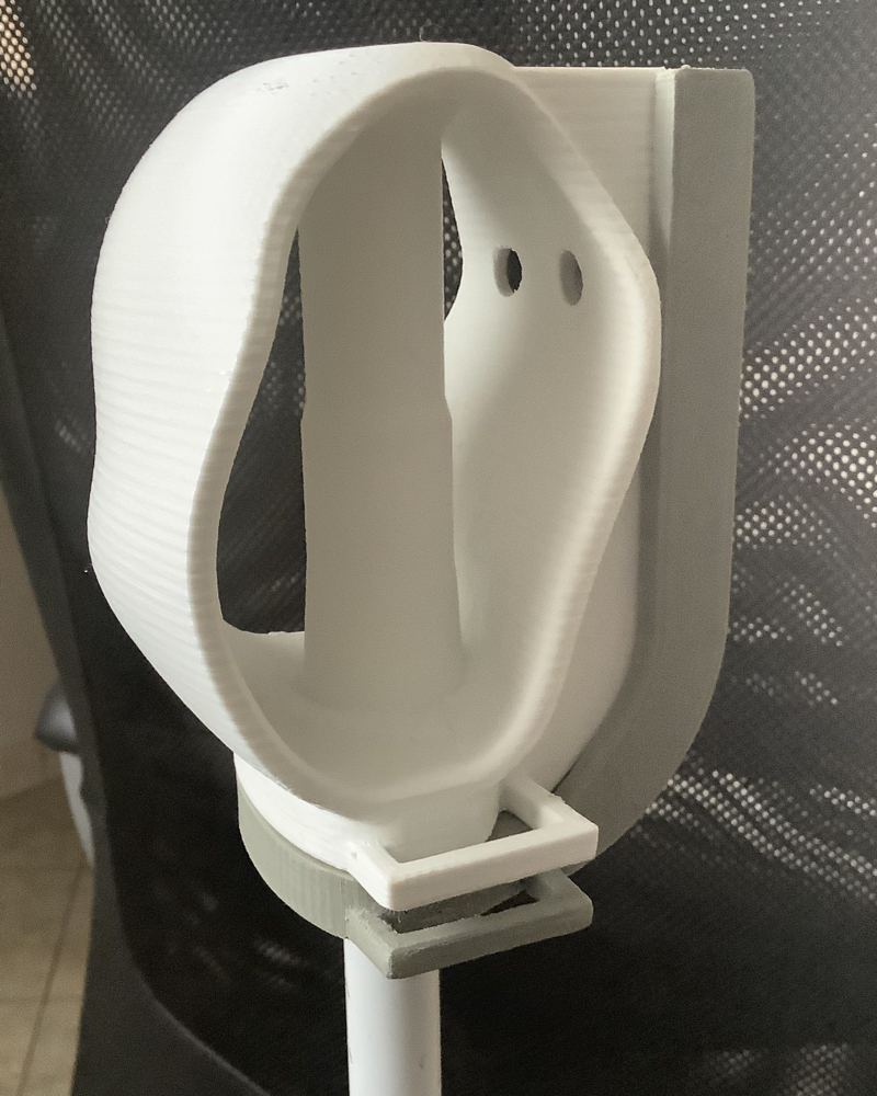
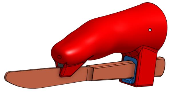
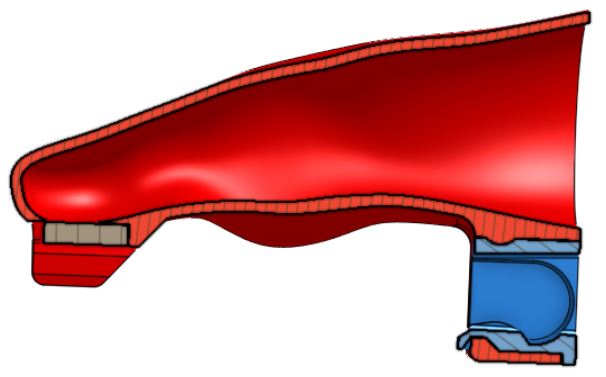
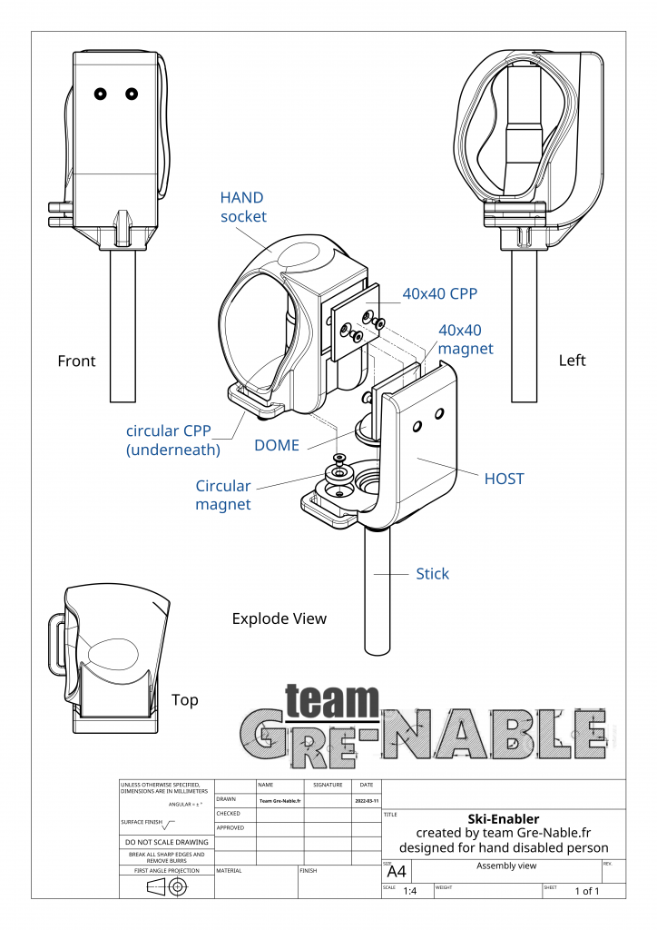
The host frame is attached to the stick. The vertical side of the host is on the outside to allow ejection of the interlocking (inwards) in case of any fall. On the inner side of the host, we can see the location where the small circular neodymium magnet aimed at vertical support will be screwed, and the rectangular magnet, more powerful, dedicated to lateral support.
L’emboitement est “collé” sur le bâti grâce aux forces d’attraction des deux aimants.
The hand-socket is “glued” to the host-frame thanks to the forces of attraction of the two magnets.
  1. The correct positioning of the interlocking is ensured by a centering dome, and a calibrated location
  2. The holding of the interlocking on the frame is the attractive forces of the main rectangular magnet (40x40x4)
  3. The second magnet (circular) facilitates vertical support and centering of the hand-socket.
-The first prototype validated the functionality of holding the ski pole and its test on a ski slope confirmed our technical choices.

Some small improvements were made to give more room for the thumb and the final version of the interlocking was printed using semi-flexible material (BASF Fusion, with shore mark 65D).
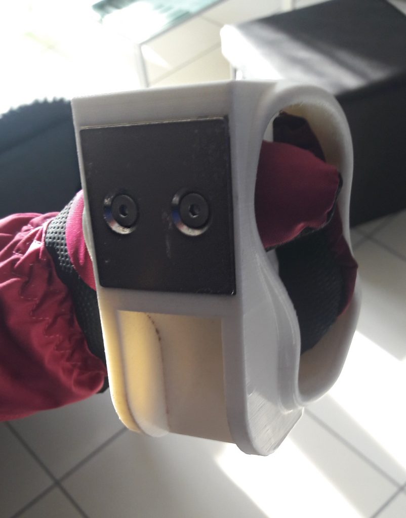
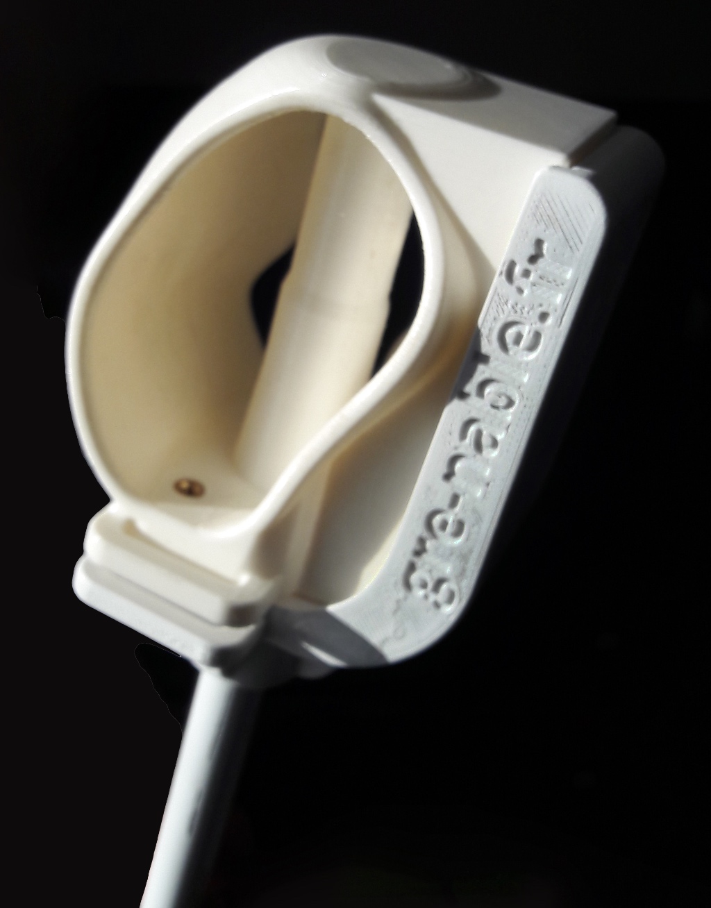
The success of this new concept quickly attracted other parents. So we reviewed (cleaning) the design scripts, so any new requests would be made quickly. The frame (HOST on the drawing) is almost generic, its adaptation to the hand-socket is minimal. On the other hand, the hand-socket being 100% adapted to the size/aspect of the hand and the type of agenesis of the child, its design will be a little more touchy.

Ces adaptations de système à la main d’un autre enfant nécessitent de maitriser l’outil de conception CAO, mais n’est pas aussi compliqué qu’il y paraît. Les fichiers STL du système développé pour Manon ne seraient d’aucune utilité pour un autre enfant. Par contre, nos développements sont open-sources et disponibles sur la plate-forme Onshape, et nous sommes toujours prêts à donner un coup de main 🙂 [© E-nable France]

These system’s adaptations for another child’s hand will require some skill using a CAD design tool, but are not as complicated as it seems. The STL files of the system developed for Manon would be of no use for another child. On the other hand, our designs are open-source and available on the Onshape platform, and we are always ready to give a helpful hand 🙂

Let’s keep in touch.


A knife holder for a child

A knife holder for a child

The context 

Lina is a 5 years old girl when we meet her for the first time. She was born with a malformed right hand equipped with two fingers. One of these is weak. She cannot flex both of her fingers, but only move them laterally as a kind of needle nose pliers. And she is very comfortable for most of everyday life activities… except for some actions that she cannot perform. And an example is holding a knife. Her parents are used to help her cutting meet, and she is used to push rice to the fork (which is handled by her left hand) with her two fingers.  

But now she has to have lunch at school, or sometimes diner in  a restaurant, and she probably feels not so comfortable in front of other children.  Thus Eric her father asks e-Nable community if someone can help in developing a kind holder for Lina.

Modeling of a fitting socket

After a first meeting with Lina and Eric, we consider that a standard e-Nable hand cannot fit the need of Lina, and we decide to develop a very dedicated knife holder.  It will be made of a socket in which Lina can insert her right hand, and some specific shapes where she can fix different kinds of knives.

Hand casting 

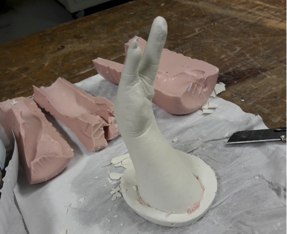
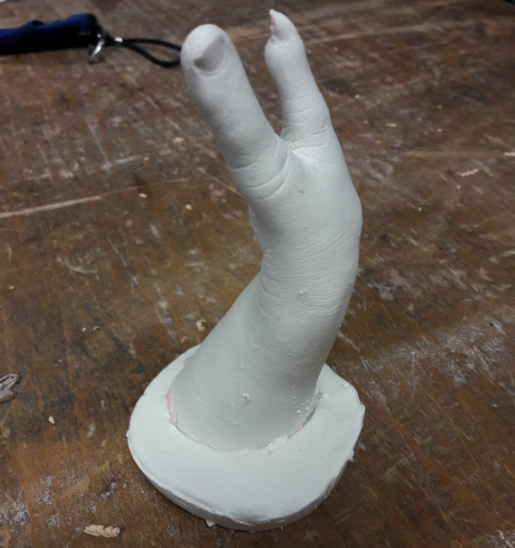
The first operation is to get a model of Lina’s hand. This is done by casting her hand in pink Alginate to get a positive plaster copy.  

Shape modification

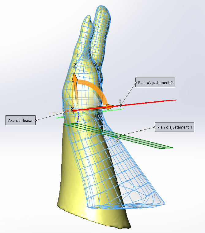
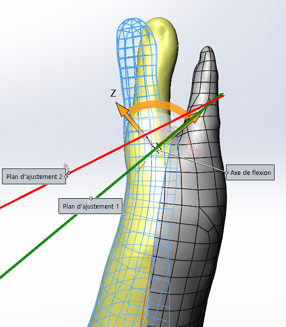
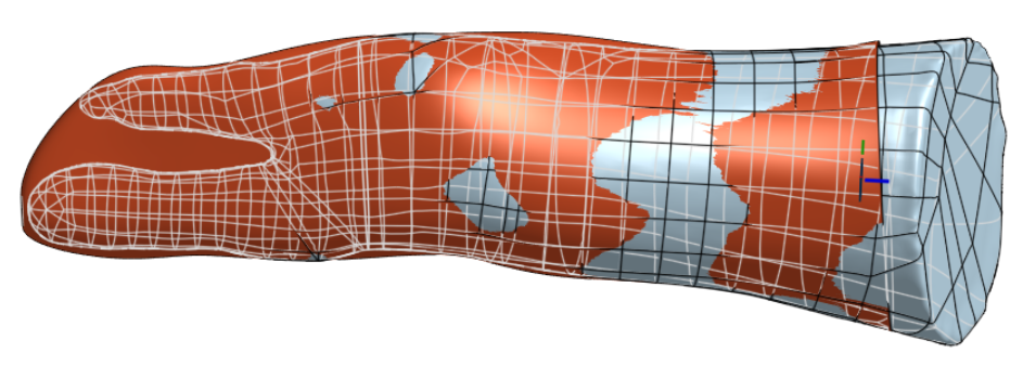
Unfortunately she bent her wrist during casting operation. After the 3D scanning and reverse engineering process that leads to a clean digital model, the next operation to get a proper model usable to make a comfortable socket is then to unbend the CAD model. This is performed thanks to a specific “flexion” function available in SolidWorks. This allows to put the hand inline with the forearm, and also to put the two fingers closer to each other.

Design of the socket

The next step is to design the socket. We come back in our collaborative CAD software, Onshape, to draw a few sections and build a “loft” that approximately fits Lina’s hand. Then two offset operations of surfaces lead to the inner and outer shapes of the socket, with 3mm gap dedicated to put a comfortable 3D fabric that can absorb moisture and can be easily removed for washing. 

Designing the knife holder

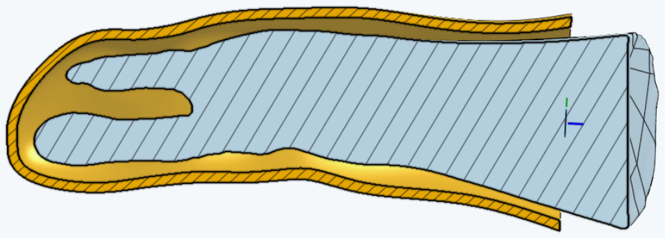
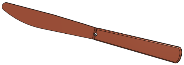
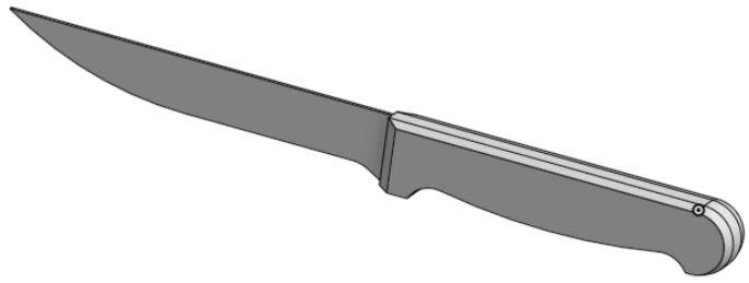
The input information for designing a knife holder it to have an idea of the types of knives that will be used with this device. Eric, Lina’ farther, provided two CAD models (he drawn by himself) of knives available at home: the “knife to push” and the “knife to cut”.


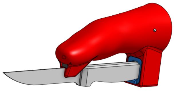
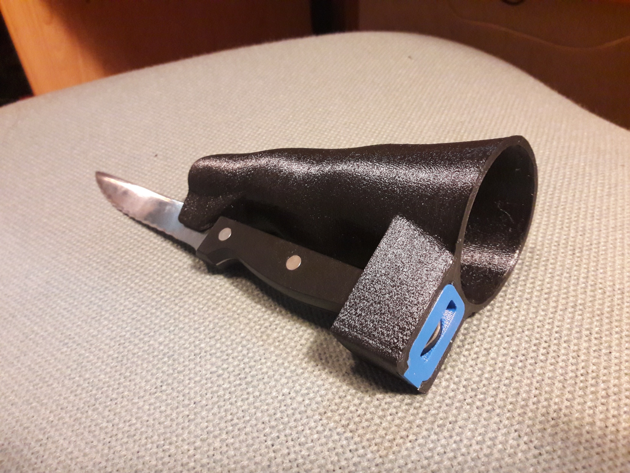
Then we started with the idea of fixing the knife handle in a flexible interchangeable part that should fit both types of knives, and to add a simple slot to center the blade. In the first prototype the blade has been tied with adaptive strap made of Velcro type band (ID-Scratch).

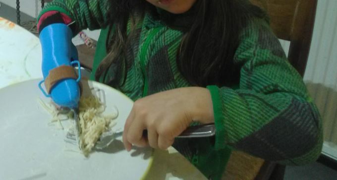
After validation of the orientation and position of the knife by Lina, for the second version the strap was replaced by a simple neodymium magnet. You will find below a photo of the first version in test (pushing knife), and several CAD views of the last version.

And then…

Lina is happy, she can eat without asking for help to her classmates;

Eric is happy, Lina eats now without pushing noodles with fingers.

Eric asked for advice because (and that’s also good news!)

  • he is in the process to learn how to design with Onshape. He already made a new insert (the blue part on screen shots above) that will fit another knife handle.
  • And he is in the process of buying a 3D printer and we hope him to become a new maker within e-Nable France community 🙂


The CAD models are available for inspiration, adaptation to other cases, and hopefully for improvements under cad.onshape.com, if you have an account (free for non profit activities and public models), you just have to search for “Team Gre-Nable : knife_holder” among the public models. 

Please just let us know if you design an adaptation of this!


Terminal Socket for Keyboard Typing & Smartphone Use

Terminal Socket for Keyboard Typing & Smartphone Use

Open source project:

This design, like all those made by Team Gre-Nable, is open source. We explain in these articles why and how they were done, the reasons for our technical choices like the means and tools we used. All 3D models are available under the Onshape environment (free access for public models). This design is accessible on Onshape by using the Search tool with team Gre-Nable.fr : manchon Jean“.

Jean’s Situation …

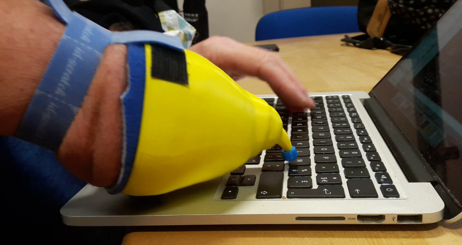
Jean is an adult suffering from agenesis of the right arm. He has his elbow and forearm only 9cm long, with very conical form and ending with a small “bud” … he has become accustomed to use among others to typing his MacBook’s. And we must admit that it is impressive with his “dexterity”. But the more and more intensive use of his computer for his work ends up hurting him and generating pain from his little “finger”. He would like to protect his skin while maintaining his dexterity he has acquired in the usage of the keyboard. He has already consulted two or three professionals who made him special appliances, which ultimately did not suit him. He then contacts Team Gre-Nable.


Molding & Casting

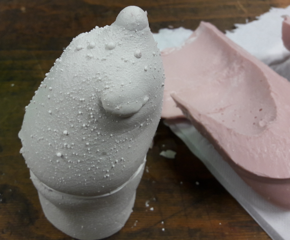
An alginate molding session provides a plaster model of Jean’s forearm and elbow. Note on the image below many bubbles that have been trapped in the hair of his arm during molding, which generates these small “balls” distributed on the surface of the plaster model. These were removed very easily with a cutter blade on the plaster. We can distinguish very well in the upper part the “bud finger” Jean used until now to type on the keyboard of his computer. In the lower part of this molding, the slight restriction of section is due to the presence of an elastic band we place intendely to clearly mark the location of his elbow during molding. This restriction will be removed (smoothed) between the 3D scanning operation and the CAD volume reconstruction.

Plaster model cast from the alginate mold.

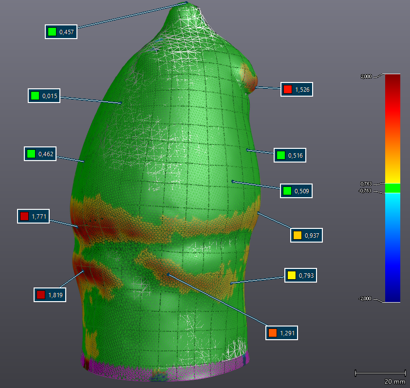
Comparison of 2 brand/types of 3D scanners.

This plaster model is digitized with a 3D scanner. We took this opportunity to compare the iSense (see also  https://3dscanexpert.com/structure-sensor-review-part-1/)  with a high-end HandyScan 700 professional scanner. HandyScan 700 .

The Handyscan will be considered as the reference tool, with a reported accuracy well below 0.05mm on this type of object.

Results of scan shows the iSense giving efficient results for this application (accuracy less than 0.7mm, average around 0.5mm) in most areas with few variation of curvature, however, in more rugged areas, errors can reach nearly 2mm. But since we foresee the insertion of a comfort glove with thickness of 3mm (blue 3D fabric visible on the featured image near the Jean’s elbow: the process of designing this comfort glove is fully described in his post), and that we can also count on the adaptability of the flesh in contact with the socket, it seems that the quality of the iSense will be sufficient to digitize this model in plaster.

Please note that a direct digitization of the arm would probably have generated larger dimensional variations. We will keep the accurate scan made with the Handyscan as we have it.

A CAD model will be created based on this 3D scanning (obviously a mesh file), and exported in STEP format for use by Onshape online webapp.


Socket Design

Two new models are generated thanks to VXelements application (associated app with Handyscan scanner of Creaform)), with offsets of surfaces of 3mm then of 5mm. We wanted to test these features in VXelements (and we were very satisfied with the results) nevertheless these surface offsets and the generation of the new volumes could have been done with other modeling tools, either on the STL model (with Meshmixer for example) , or on the reconstructed STEP model (Fusion360, Onshape, etc …). You can read our post “Création d’un Multi-tool holder“for an example of using the “Surface Offset” function in Onshape.

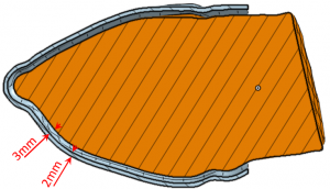
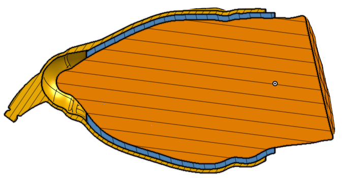
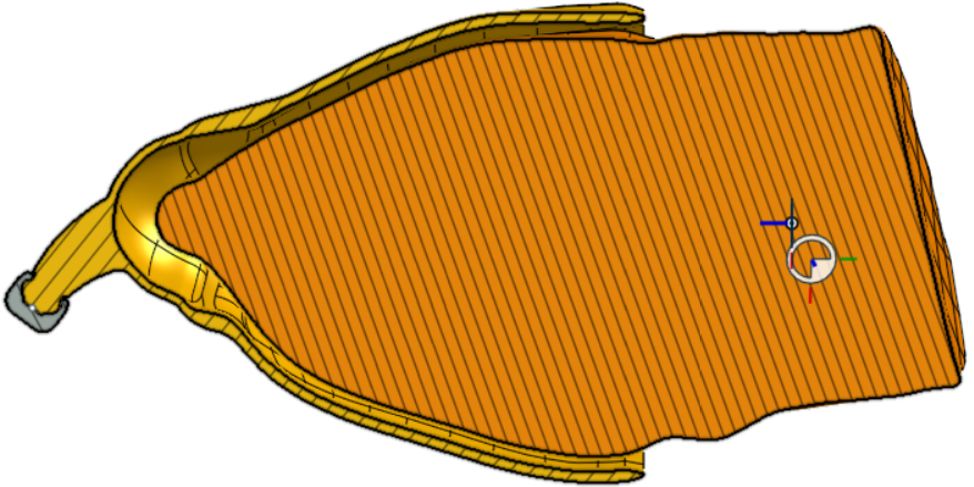
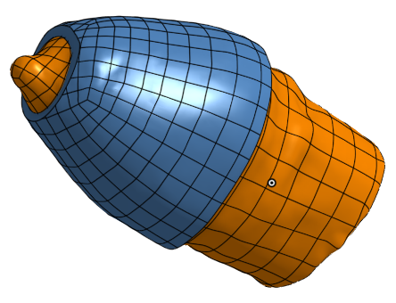
The three volume models obtained, which we will call “ arm “, “ arm + 3 ” and “arm + 5” are imported into Onshape in STEP format. A boolean (volum) subtraction operation between “arm + 3” and “arm + 5” makes it possible to obtain a socket with a thickness of 2 mm thick, 3 mm away from the arm.

emboiture

ARM and initial socket


Clearance around pinky

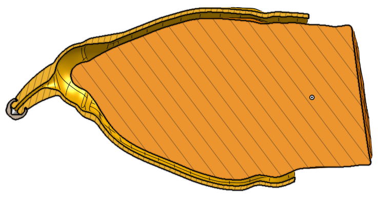
An additional offset of the surface, followed by some cuts and re-assemblies of volumes allow us at this stage to release a significant clearance at the end of socket, which will avoid the contact between the Jean’s finger and the socket. This protection is the main element of his design “specifications” transmitted to us, so we pay special care for this!

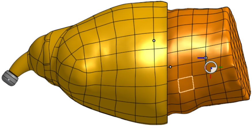
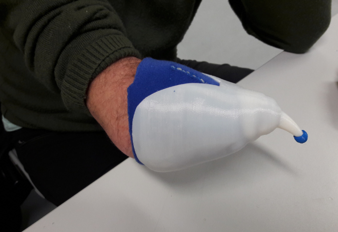
Then we add an artificial “finger”, which will be equipped with a flexible tip ( made of NinjaFlex) to allow a soft touch with keyboard’s keys.

Socket and finger, external view.

Preparing 3D fabric, and clearance provided around Jean’s bud to prevent any injury.

Socket and finger, section view on.

3D fabric : finger clearance.

Adaptation for touch screen

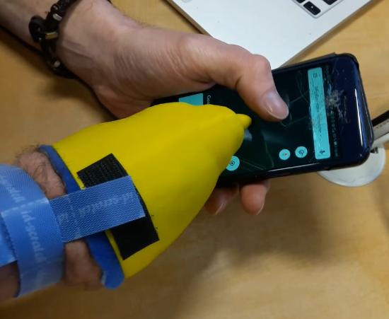
Like most of us Jean uses a smartphone or tablet and thus a touch screen.Could he take advantage of this artificial finger to manipulate the apps on this type of screen ?

I had studied this issue few months ago, and I came to the conclusion that it should be possible. Indeed most of the current touch screens are capacitive, and speaking without too technical terms (which I would not control for that matter!) the touch screen detects a variation of potential generated by a slight leak of electrons when the finger touches the sensitive surface. It “would be enough” therefore that the end of our plastic finger (in this case the foam cap) would be connected to a sufficient electrical mass to provoke a slight electrically discharge during contact with the screen. The solution is …

  • drilling a small channel inside the artificial finger to insert a flexible electrical wire,
  • to replace the current printed tip (made of Ninjaflex) with an conductive tip retrieved from a smartphone stylus,
  • and to connect the wire to a metal mass, and possibly touching the skin of the user.

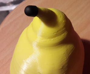
Channel to end of the tip for the wire

Wire exiting toward conducting tip

Former stylus tip placed on the finger

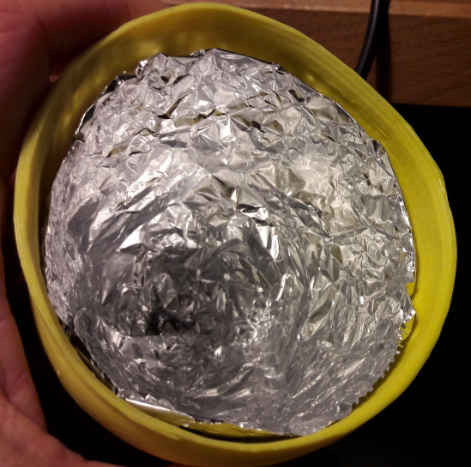
Electric mass made of aluminium foil (kitchen product)

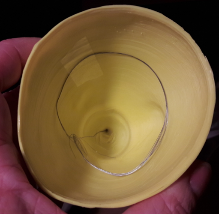
Electric wire as an alternate solution

The smartphone stylus tip was taken on a stylus of this type.  Tests show that direct contact with the user’s skin is not necessary and good news as well ! What’s more, aluminum foil is not essential either. The system works very well with just a turn of wire in the socket, wire which is located about 3mm (the thickness of foam “3D fabrics” of comfort) of Jean’s arm.

Results of first tests

The second meeting with Jean (after the molding) was really satisfying.
remaining point was to imagine a way to maintain the socket well in place around his forearm. The first tests were done by placing two pieces of adhesive Velcro on the edge of the socket, and placing another strip of Velcro around his arm. The following videos taken during the first minute of use in each context (keyboard and touch screen) show that Jean will undoubtedly succeed in appropriating this new tool … if it is already done from this moment.


Very first try, Jean typing on his Mac.

Jean’s first test on his touch screen. See how smoothly he zooms with his left thumb and right “index”!

Holding the socket on the arm

The very conical shape of the Jean’s forearm does not allow effective hold by simply clamping in this area. The first tests showed the feasibility of maintaining a strap around the arm, but we are looking for a solution that would be easier to handle, and that would avoid a localized tightening certainly not comfortable.

It seems then that the proposal made by Dominick Scalise to use a fabric sleeve for some prostheses would fit here.
A first test is done by cutting a sock … it seems to work well, and we propose to Jean, by email, to test himself this solution with the socket it uses.  

Meanwhile, we also offer a socket version printed in TPU (semi-flexible material) rather than PLA, to further improve comfort. Let’s not forget that John wants to use this device every day for several hours. 

In our third meeting, Jean introduced us to the fixation solution he found : he replaced the idea of ​​the sock with an ankle (usually used in the case of a sprain) that provides homogeneous and very efficient clamping. Just find the right dimension, and he will use or not the complementary elastic straps that come with it.

The TPU version seems to seduce him on the comfort side, and he plans to reduce the length, or even cut a slot on the side … what we do on the spot.

Printed release with TPU with slots. Please note the “glove” made of 3D fabric.

Hold with ankle (it may be necessary to use the size below)

Orthosis for a Cook

Orthosis for a Cook

Yann’s Life Status :

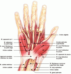
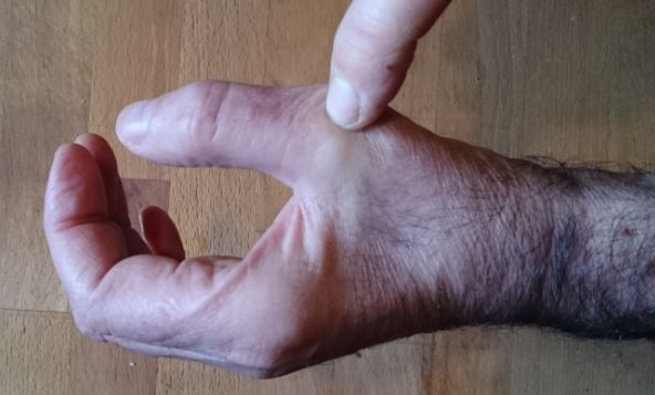
Yann is an adult suffering from a pathology of the nerves (an NMMBC [1] for topic’s specialist) which in particular renders ineffective the control of a muscle of his left thumb, the one which brings the thumb into the position of opposition towards the other fingers (aptly named “opposing thumb muscle”, see image below). The muscle atrophies. Yann can therefore no longer have a normal grip with his left hand, which is inconvenient for a cook (to hold a bread, a sausage, an onion … while his right hand cuts slices for example).

[image en provenance du site Doctissimo]

A need for an orthosis

He would therefore need a mechanical assistance to place his thumb in opposition, but he also needs to be able to move back his thumb when needed in the plane of the palm for other manipulations (like cutting thin slices of salmon for example).

Occupational therapists in the hand surgery department at Grenoble University Hospital can build a rigid orthosis that will keep Yann’s thumb in opposition, but this will prevent him from raising it to put his hand flat back on the working table. The orthosis to be designed must also be compatible with the hygienic constraints associated with the cooking profession, and to be as compact or invasive as possible to minimize the inconvenience of wearing over a long period. So his occupational therapist advised him to contact our team (“makers” of e-Nable France) to envision if 3D printing technology could produce an adapted orthosis to his situation.

Methodology

The project was first entrusted to a group of engineering students from Grenoble-INP Génie Industriel [2]. After a very detailed study of the needs, and the usage of a 3D scanner to model Yann’s hand, they carried out a benchmark which confirmed that most of the existing orthosis for hands are made from thermo plastic mesh which remains rigid after shaping. Unfortunately this would prevent Yann from bringing his thumb back into the plane of the palm. But the scanned model made it possible to print an exact copy of Yann’s hand to quickly test the placement of various orthosis prototypes. However, this does not make it possible to judge the effectiveness of maintaining the thumb in the desired position. Recurrent interviews with Yann were necessary to fully understand the solution. All this work resulted in a printed orthosis made from a flexible material (TPU) which wraps around the hand, hooks to the base of the index-middle fingers, and maintains the thumb in an opposable position, without preventing the return of the thumb to the flat hand position. The result of this study is promising, but keeping the thumb in opposition still seems insufficient to Yann, the orthosis is a little too bulky to be used over a long period by Yann as part of his job.


Design Steps

For this development we followed an iterative user-centered design process, which steps are defined below.

Step 1 :

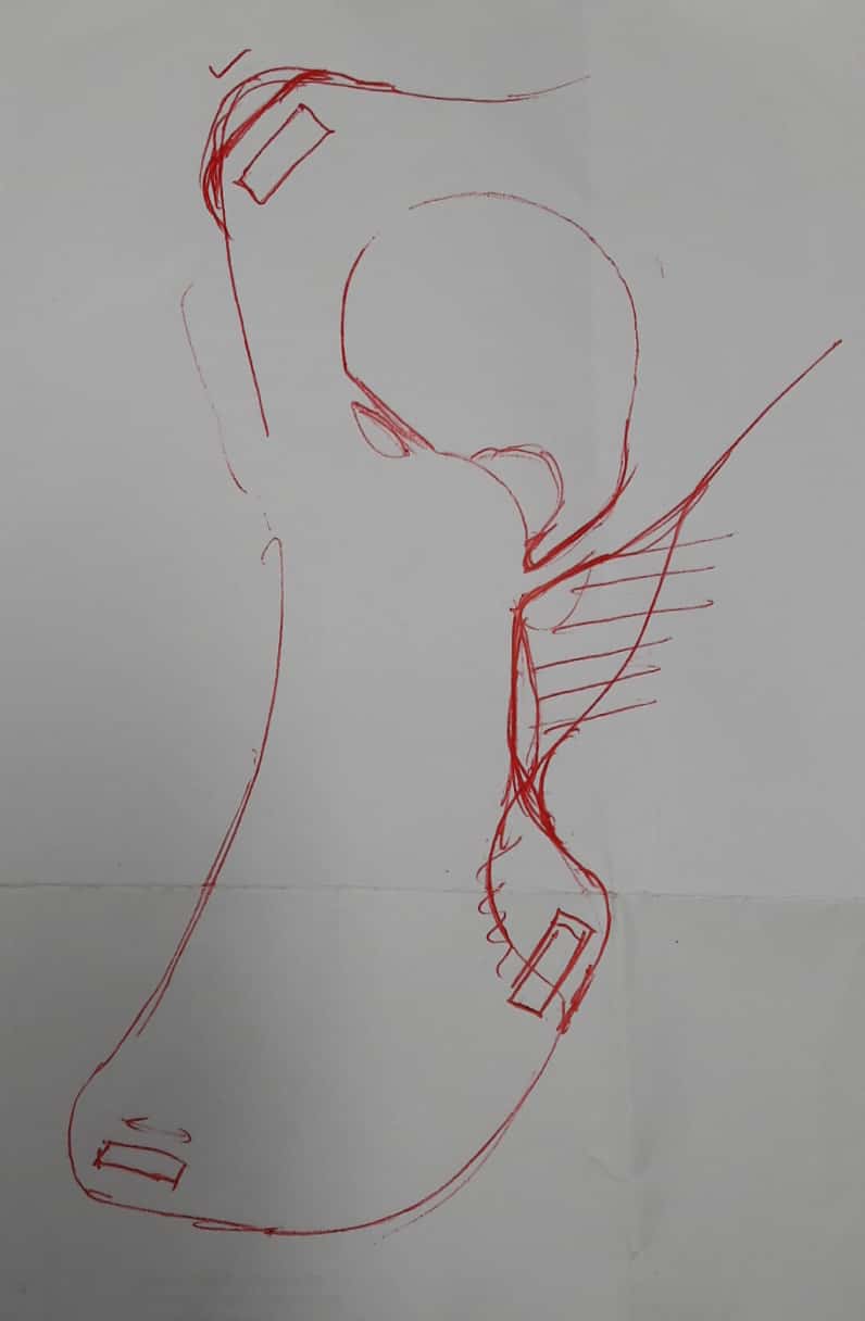
During a meeting with Yann, the observation of the previous prototype on his hand, and gathering his feelings and expectations as the final user, we generally come out with a drawing on a paper, which provides the raw aspect of the future orthosis, highlighting the evolution compared to the previous version. See two examples of such sketches on the pictures opposite.

Step 2 :

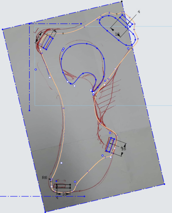
Uploading the hand drawing into the CAD system then allows sketching a digital model of the outlines of the orthosis (mainly by Spline curves).

Step 3 :

After adjustment of the sketch curved lines to achieve a ‘nice’ appearance, the base shape is obtained by extrusion with a thickness of 1.6mm to 2mm depending on the flexibility we expect.

Step 4 :

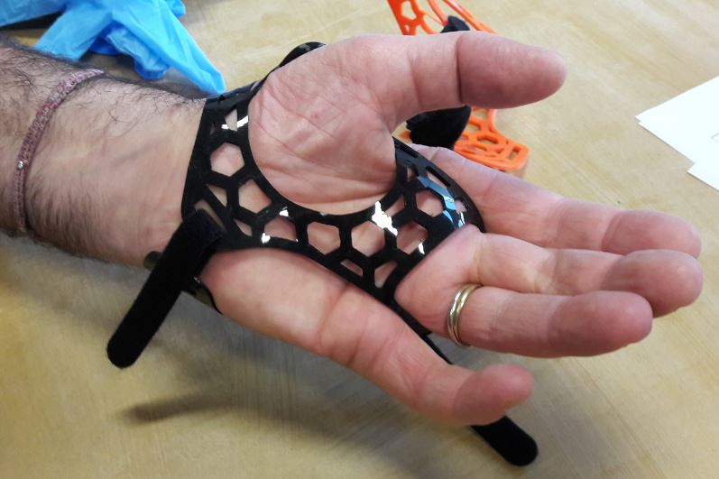
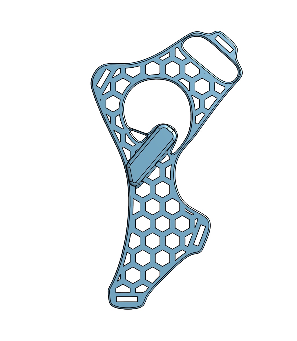
Parallel line cut allow keeping only the contour boundaries (3mm to 4mm width). The holes will later be replaced by honeycomb structure.


Step 5 :

Design of a matrix with honeycomb shape. Various parameters are adapted to properly fill the orthosis. Not too much material and not too much holes.


Step 6 :

Extrusion of the honeycomb structure, removing of the outer extrusion to keep only inner elements, and finally merging with the boundaries.


Step 7 :

Designing, extruding (thickness of 3mm to 4mm) and merging the blocking “blade” that will push on the back of the thumb.

Note also the small link added on the left side of the blade, to help pushing the thumb.


How it works

The idea is that the honeycomb orthosis fits the hand of the patient, and the thicker tongue, that is more rigid, pushes the thumb towards the opposition configuration. So wearing this device maintains the thumb in this position. But simultaneously, the whole orthosis being printed with quite flexible material, the person can overcome the small force provided by the tongue to extend his thumb and get the hand flat when needed.

The way to wear it is presented on the series of pictures below.


About the material we use

For this kind of device we use either TPE (thermoplastic elastomer) which is a “flexible filament” or TPU (Thermoplastic Polyurethane) which is a “semi-flexible” filament.
The specific behavior of these materials is characterized by its hardness, expressed on a standard “Shore” scale. Be careful there are several scales. The ‘A’ scale is used for softer materials (like rubber band), and the ‘D’ scale for much harder ones (like solid truck tires).
The TPE filaments we use here feature between around 86 Shore A.
The other type, TPU, generally features a hardness of more than 95 Shore A, and up to 98, which is really more rigid.
So depending on what behaviour you want, you can change the material, but don’t forget the other main parameter you can adapt to get a more or less flexible part is the thickness (and infill percentage) of the printed part, and the thickness has a huge influence on the part’s flexibility or stiffness.

Improvements


This first draft of project having given interesting results and allowing to consider still some improvements, team Gre-Nable ensure the follow-up, and two additional interviews with Yann made it possible to reach a usable orthosis with a slightly thicker support tab behind the thumb.

The orthosis is also smaller and therefore less invasive than the first versions, more flexible, it clings to the middle-ring fingers (which makes it possible to better pull the thumb in opposition). The Velcro straps are also reduced in width for less discomfort.

Yann seems satisfied with the help provided by this orthosis, while leaving him the freedom of bringing his hand flat when he wishes. The fact remains, however, that the crossing of the plastic filaments between the fingers is still troublesome.

Yann therefore returned visiting his occupational therapist who placed a protection consisting of a very thin adhesive tissue, which should avoid injuring the skin between his fingers.

Achievements

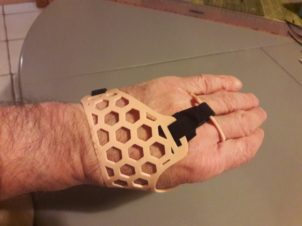
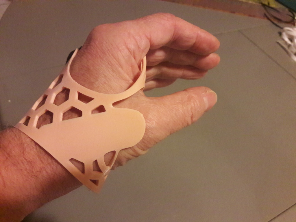
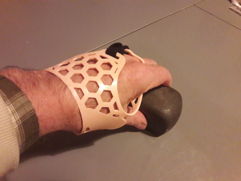
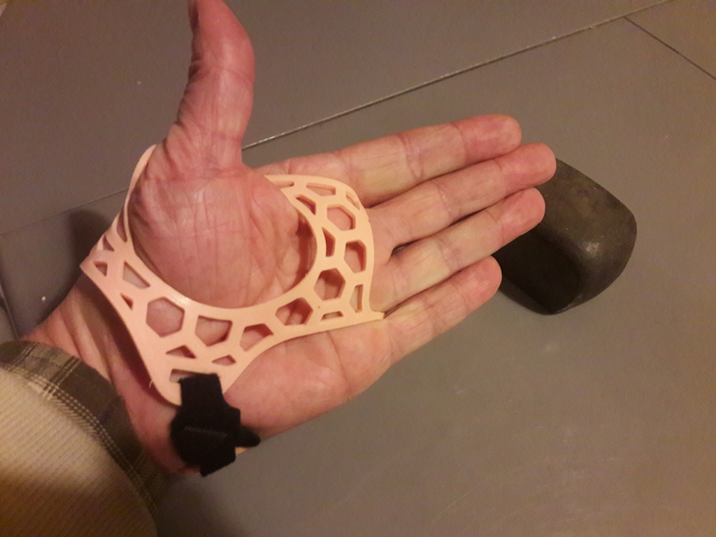
Note that the following images are made on the hand of one of the designers, and the orthosis does not really fit, but this is mainly for demonstration purpose.

Picture 1 :

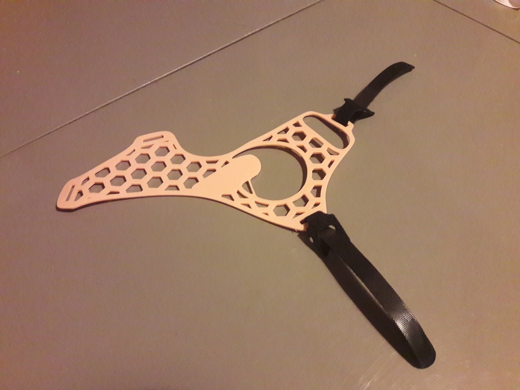
Here is the orthosis ready to be used, with two Velcro straps.

Picture 2 :

How to put the orthosis on the middle and ring finger, then on the thumb.

Picture 3 :

How the Velcro straps are fixed on the back side of the hand.

Picture 3 :

When the Velcro straps are tied, the configuration of the thumb is naturally opposed to other fingers…

Picture 4 :

… and allowing a heavy grasp on an object.

Picture 5 :

But the flexibility of the TPE material still allows the user to extend his thumb,

Picture 6 :

… and put the hand flat on the table.

Testimonies

“Regarding the orthosis, all improvements made the orthosis efficient and more comfortable, however, it’s still not sufficient to wear it for a long time (duration greater than 1 hour). I therefore only use it on well-defined tasks that I group together as much as possible, and efficiency is there ! […]

Thank you to the whole team, thank you for your actions which allow a few happy people to retrieve a part of their autonomy. “

Yann.

Cook

“The orthosis developed by the Gre-Nable team:

  • it frees the mobility of the wrist compared to the first draft,
  • it allows passive opposition (by the splint) and the active feedback of the thumb in the plane of the hand,
  • no bulk in the palm – disinfection is possible by immersion,
  • not very bulky: fits within a vinyl glove

Yann retrieves a function without it being to the detriment of another.

This is where it is powerful !

Yann's occupational therapist

Grenoble hospital

To access the orthosis model we developed

For all our developments, we use a professional web-application with free access for makers named : Onshape .
If you want to use it, you only have to register. It is a very powerful and rather easy to learn Parametric CAD application developed by the former designers of SolidWorks.
All the projects developed using Onshape’s free license are public, therefore accessible to everyone for reading and copying in their environment.

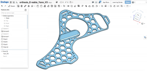
orthese

Orthosis seen in Onshape

After logging into Onshape, just search for the word “Orthosis” to find all versions of this orthosis (among a few others), or “orthosis_Gre-Nable_Yann_V6” for the series of latest modifications shown in the images above.


Notes :

1) Multifocal Motor Neuropathy With Conduction Blocks causing motor deficit in part of the left hand.

2) Many thanks to the entire team of engineering students for their significant contribution to this project : Valeria Baghin, Adriana Camacho, Lucas Delaire, Dorian Gomez, Orianne Kassis, Bhargav Patel

Design Of An Assistive Upper Limb

Design Of An Assistive Upper Limb

Here is the final report written by 3 graduate students who worked during 4 months full time to build a proof of concept for an assistive system dedicated to ease utilization of e-nable printed apparatus. They together investigated the state of the art in low cost assistive upper limb prosthetics, and proposed and tested a set of technical solutions.
Thanks to Júlia FIGUEREDO DE ALENCAR, Khumbo NYIRENDA and Nicholas TYRIE, who came from the University of Bath (UK) to perform this semester in the school of Industrial Engineering in Grenoble, for their high involvement in this project and for the quality of this report.

Philippe

Thesis advisor, Industrial Engineering School, Grenoble Institute of Technology

You can read or download the report of the 3 students : Responsible_Design_Final_Report. Happy readings.

Wrist Lock System: Relieving wrist bending

Wrist Lock System: Relieving wrist bending

Context:

Classically, bending the wrist enables handling objects with an E-nable hand prosthesis (Raptor or Phoenix). But, we identified that this bending movement, necessary to trigger a grip, led to tire the user of the prosthesis with time.

After Nathalie has experimented her hand prosthesis (see post), it became obvious we had to find a solution to relieve her wrist muscles. Nathalie is an adulte who suffers from an amputation of her right hand (after her wrist) after a healthcare-associated infection. Once she contacted E-nable, she was equipped with a first customised prosthesis. However, as she used it regularly – to handle tableware, purse, or to bike – the fatigue of its muscles becomes too important.

Need and process :

It becomes necessary to enable a grip position of the prosthesis without effort from the user of the prosthesis. Additionnaly, this feature has to be as less bulky as possible and easy to use.

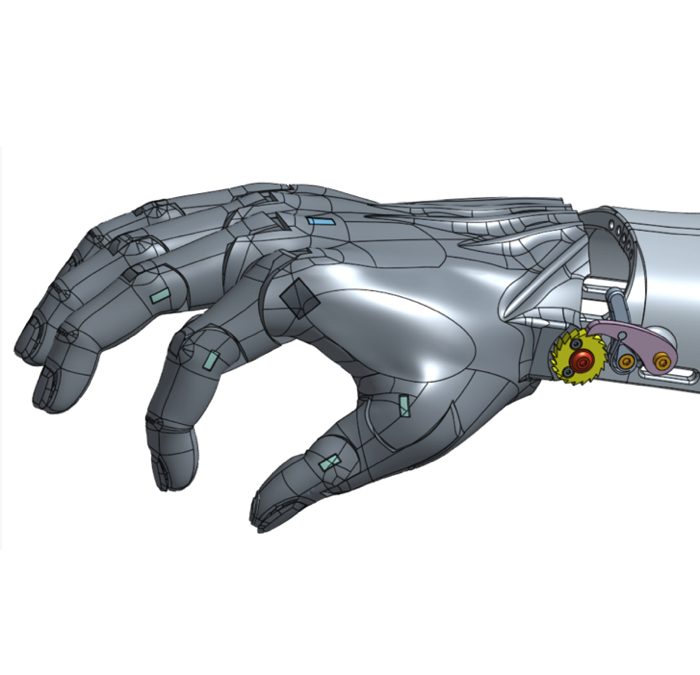
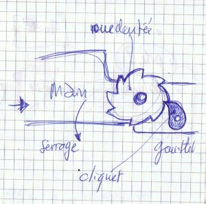
Different solutions were considered to maintain the tension in the finger wires in order to lock the grip position. However, no trade-off was found out. As an alternative, we looked for a system locking the hand in the grip position with no effort. Thus, below proof of concept has been used as a guideline, based on a ratchet working principle.

Row idea, based on ratchet working principle, for locking the grip position of a hand prosthesis with no effort from the user.

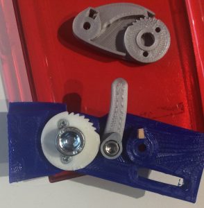
To approve such a concept, a first prototype has been designed and printed. Palm and gauntlet proxies have been replaced by simplified parts, printed in blue on below pictures.


Proof of concept, every parts were printed in PLA

All the design was realized on « OnShape » for all the advantages listed here.

Design : first version

Once the proof of concept approved, a first functional version has been realised:

First version of the « Wrist lock». On the left, in open position. On the right, in close position.


Design

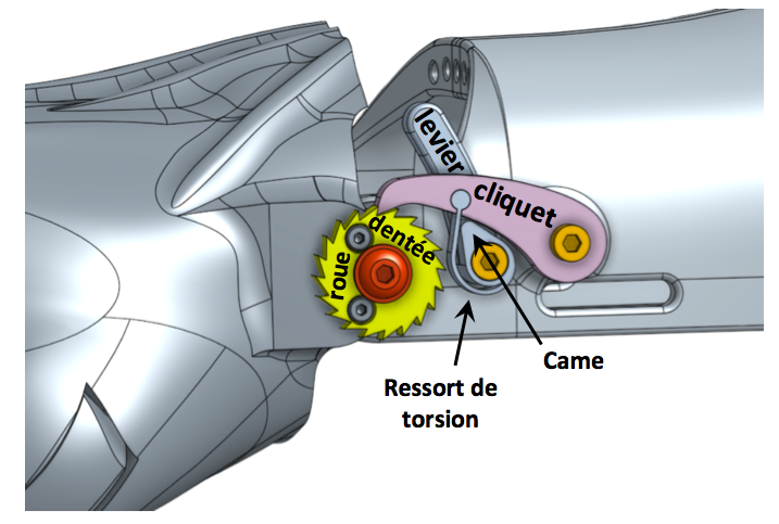
On the kinematic side: the lever cam, as in final version lifts the tooth (cliquet in french) to the open position, when the lever is pulled to the right hand side. The cam is then locked by a small hole in the tooth.  Le flex spring, printed in Ninjaflex, is compressed, to lock the open position. When the user pulled the lever on the left hand side, the flex spring lowers the tooth. This same flex spring maintains the contact between the tooth and the ratchet (roue dentée in french) by compression/extension alternatively.

On the material side, we started by printing tooth and ratchet in PLA and iGlidur (IGUS). But strain wear due to the ratchet/tooth contact were too important. So finally, we machined them in metal (aluminum/steel) to limit wear effect and to support efforts generated by an adult (for instance, the screws used to attach the ratchet to the palm quickly get loose because of these efforts. They have been replaced by two nuts-screws). Ratchet was bought at a specialist and tooth was machined in our hackerspace with a CNC DIY. Notice that the « wrist lock system », in its final version could be nevertherless fully 3D printed if the final user is a child since the generated effort would be lower.

First observations after print and assembly

After assembly, the system works well. However, we observed quickly a permanent deformation of the flex spring, mainly in open position. Likewise, the cam, in PLA wears against the metallic tooth

So we have redesigned these two elements to make the system robust. Purpose was to avoid the wear of the cam while not loosing the elasticity of the spring.

Second version

For the second version, a torsion spring has been introduced to solve both previous drawbacks: 

Second version of the « Wrist lock system ». On the left hand side, the cam and the flex spring have been replaced by a torsion spring. This spring link the lever to the tooth. It lowers the lever and maintains the contact between the ratchet and the tooth in close position. Likewise, when the lever is in open position, the spring raises the tooth. On the right hand side, the spring has been designed with the helix function of Onshape.

Design

We have first considered the wear issue. This wear comes from the friction between the cam and the small hole in the tooth. This contact is necessary to switch between open and close position. So both features have been deleted, replaced by the torsion spring. It is now a part of the lever and slots into the tooth. Thus, both part are solidly linked. So, tooth can switch between open and close position when the lever is pulled toward the right or toward the left respectively, through spring action.

Then, when the lever is pulled toward the left. Tooth switch in close position. Then, when the wrist bends, torsion spring maintains the contact between the ratchet and the tooth by means of its elasticity. Thus, the lower part of the tooth, from version #1, becomes useless and is deleted. 

In this new configuration, the torsion spring does not require to bear high efforts. Indeed, beeing attached under the tooth, it is only used to i-maintain the tooth in open position when the lever is on the right, and ii-maintain the contact between the tooth and the ratchet in close position. Such low efforts limit the risks of wear and failure of the system.

Observations after print and assembly

After assembly, the system works well. However, the torsion spring is not strong enough to switch the lever to the open position when the tooth is in contact with the ratchet. Likewise, in close position, when the wrist bends, the spring is in contact with the ratchet and so wears.
Some final adjustments are then necessary.

Final version and finishing touch

In its final version, lever and tooth have been pulled away from the ratchet (a few milimeters) to avoid generating friction between the ratchet and the torsion spring. The cam lever, from version #1, has been re-introduced to help switching from close to open position. The torsion spring then ensures to remain in open position:

Final verson of the « Wrist lock system ».  The cam lever has been re-introduced but only to help switching from close to open position. The torsion spring then ensures to remain in open position.

After assembly, this version is retained.

Finishing touch

Once the final design retained, two finishing touches have been added:

  • A spacer is mounted on the ratchet to protect Nathalie from the sharp metallic teeth. 
  • A cover is added for aesthetic purpose.

Finishing touch for the final version of the « wrist lock system ». On the left hand side: a protection spacer to avoid any contact with the sharp metallic teeth of the ratchet. On the right hand side, an aesthetic cover.