
Equilibras – “A Real Game Changer”
Foreword
At the end of 2022, during the delivery of a device to the PRM department of the CHUGA (a walking stick) for a young agenisia patient of Véronique (our favorite occupational therapist), we discovered Mila (see post: https://www.gre-nable.fr/coudiere-active-concept/ ) playing with the pieces of a puzzle, moving her arms with no apparent problems. Each of her arms was supported by an articulated device that held her forearms in a horizontal position, replacing the action of her biceps. Freed from efforts of holding her arms horizontally, Mila discovered movements she’d never done before and looked radiant. These two devices from the PRM department, originally designed for senior citizens, were being tested on young children on an experimental basis.
The discovery of this device piqued our interest in creating a child-friendly solution that could be permanently available at home (rather than in hospital), financially accessible to all families and completely open-source.
With this in mind, team Gre-nable launched its own project, the “industrialized” result of which would later take the name Equilibras.

Purpose of Equilibras
To improve balance, arm coordination and compensate for insufficient muscle strength in children with arthrogryposis.
The project began in January 2023 and the last pair of Equilibras was delivered at the beginning of September 2024. To date, two families have already received a pair of Equilibras for their child, and CHUGA’s PRM department also has a pair of Equilibras at its disposal for the development of a “therapeutic protocol” and the training of prospective parents in the use of the device.
It was a fairly long project, with an iterative approach, producing numerous prototypes and quite a few mistakes! The design was a brilliant achievement by Gérard, who was very inventive, as we started from a blank page, taking only the specifications from requests expressed by the PRM occupational therapist.
Specifications
-
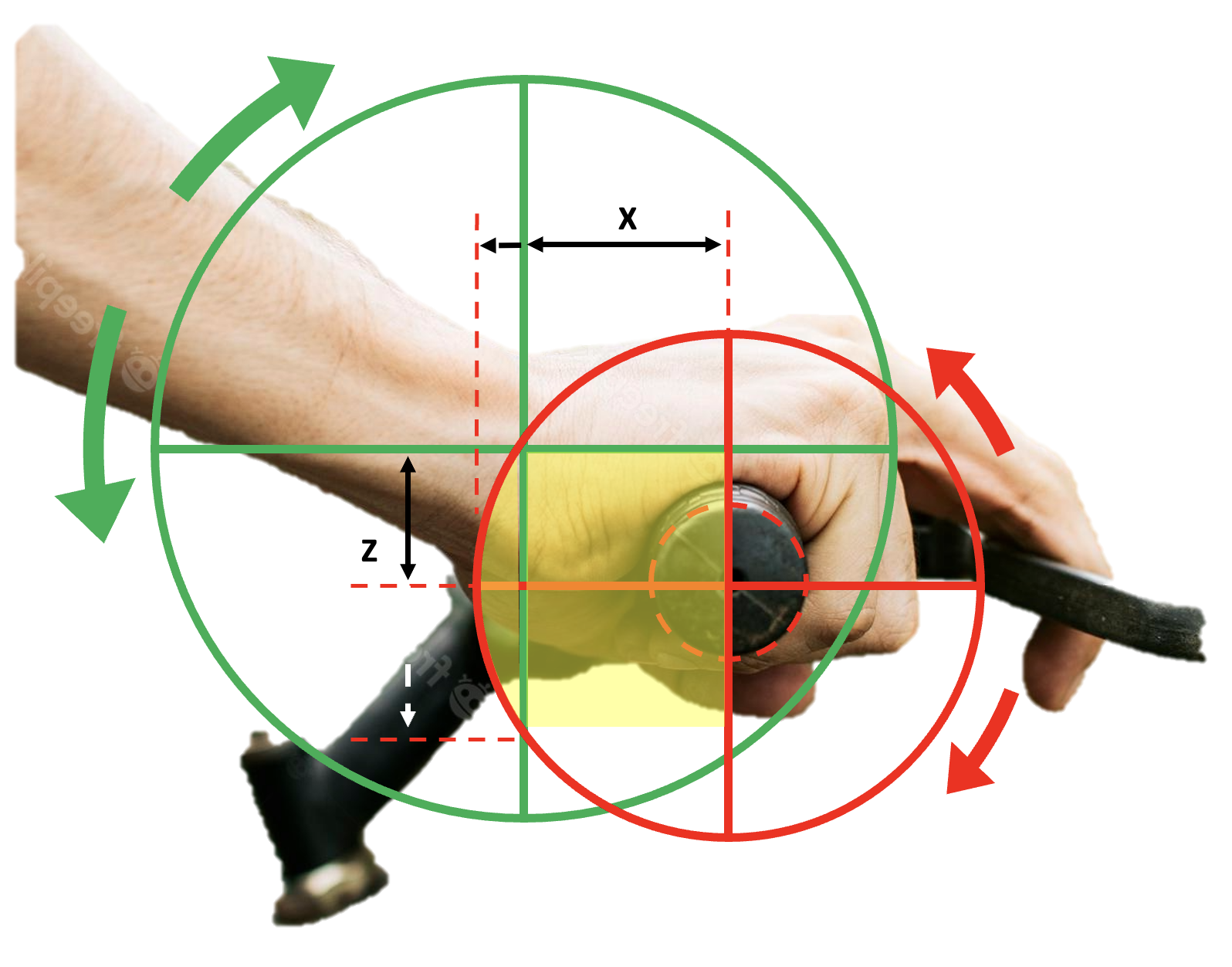
- Horizontal coverage 600 mm x 500 mm,
- Vertical clearance 350 mm
- Compensation 0.2 to 1 kg,
- Hacking of off-the-shelf components: gas spring compensation (kitchen cabinet device)
- Standard bearings, standard screws,
- Use of our usual makers (3D printer, CNC, laser cutting),
- Ability to be built by other makers (open-source distribution).
This project was the passion of our LOGre association [Laboratoire Ouvert de Grenoble], a makers’ collective to which team Gre-nable belongs, which enabled us to benefit from all the members’ ideas in designing the (adjustable) compensation system that will support each of the child’s arms. And wegot hundreds of ideas!
From the very start, it was clear that 4 sub-assemblies would be needed:
-
- A base to attach to the table,
- A pivoting arm with several segments (2 or 3),
- A balancer arm,
- A swing to accommodate the child’s forearm.
In other words, 4 perfectly independent sub-assemblies that could have their own development cycle
The base
Bracket (table clamp) for attaching to exercise table, adjustable for balancing.

The pivoting arm
3-segment articulated arm provides complete coverage of the desired space, with great flexibility of movement.

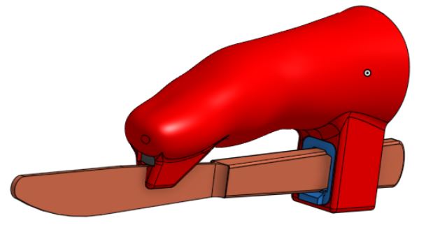
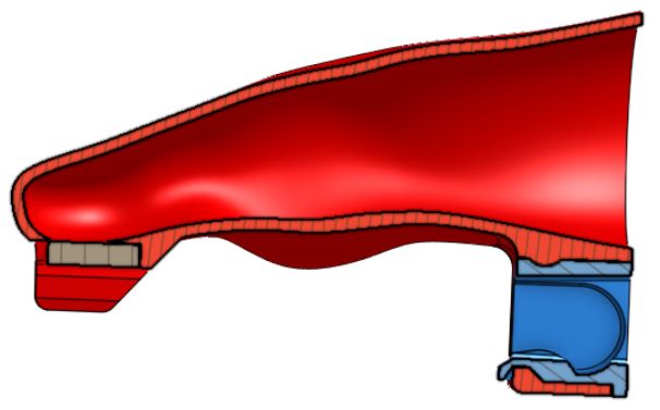
The balancer
Pivoting device controlled by a gas piston to balance the mass of the child’s arm. The system is adjustable to compensate the muscularly weakness of the child

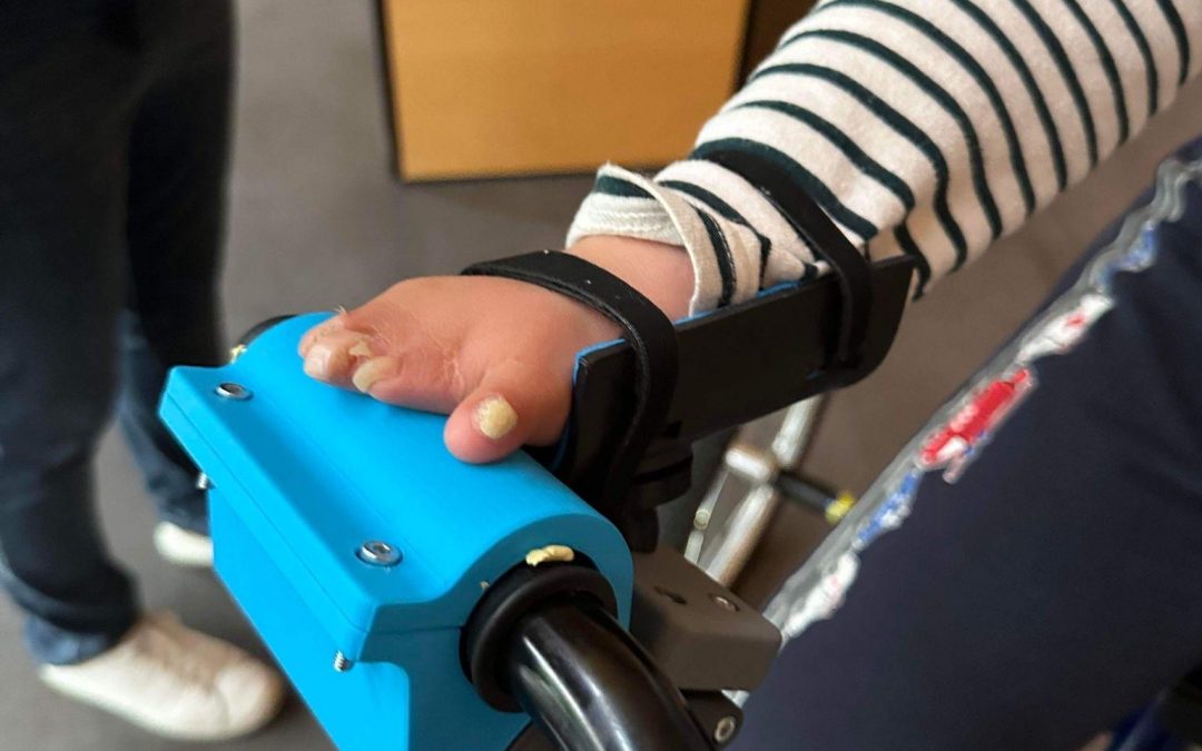
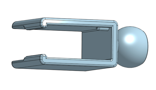
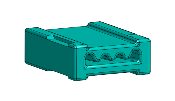
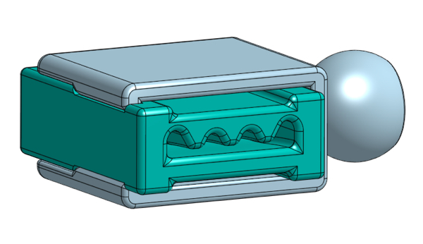
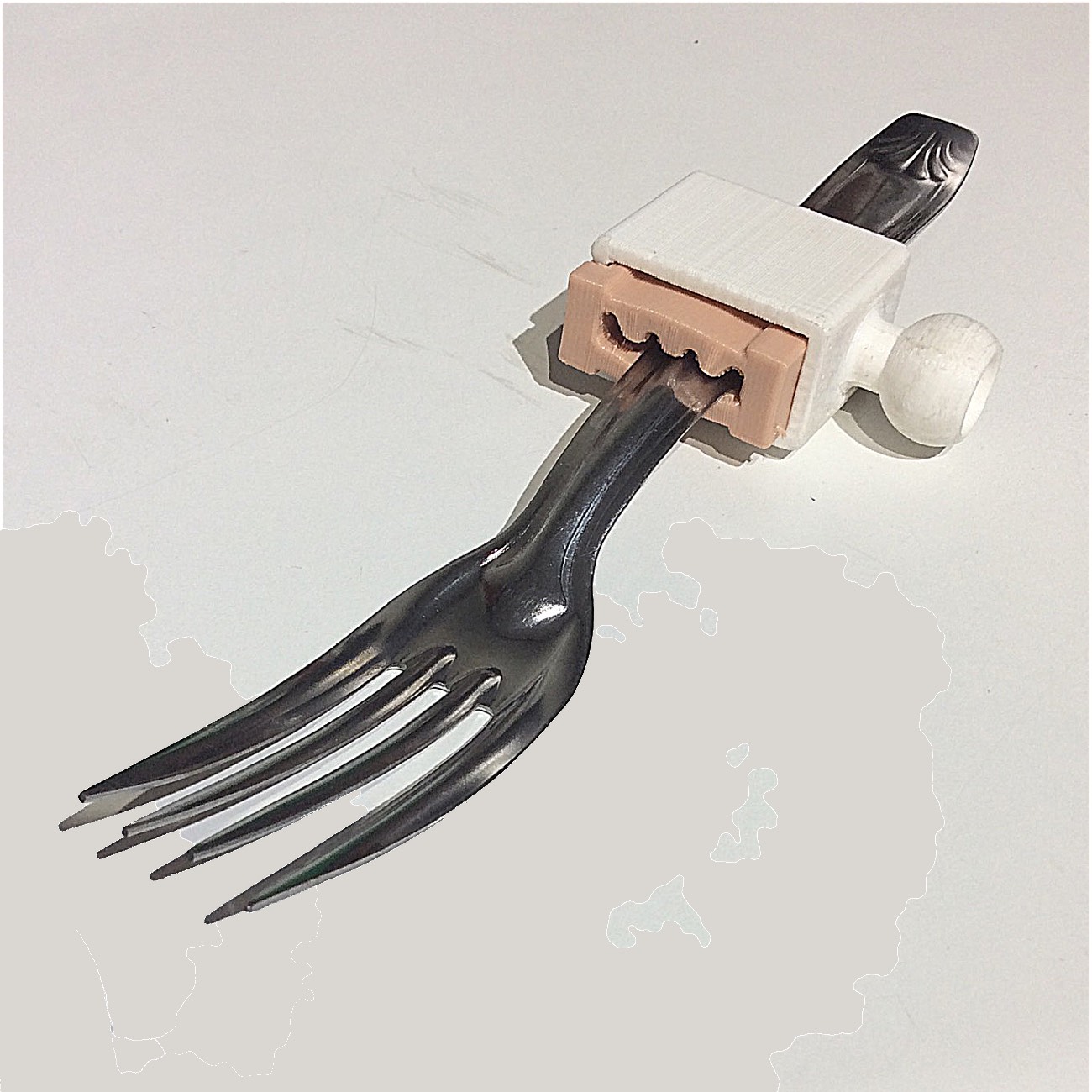
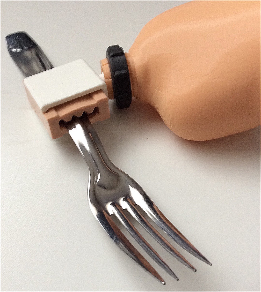
The swing
A swing in which the child rests his arm.


Feed back and outcomes from professionals
A child’s development depends on being able to use his or her upper limbs for activities such as eating, washing, catching and, above all, playing! Play is an indispensable source of psychomotor experience and learning for proper development. Similarly, the development of motor skills in the lower limbs leads to standing and walking.
In the pediatric PRM occupational therapy department at Grenoble University Hospital (MPR CHUGA) we regularly see children who need to be helped to work in an “active assisted position”, i.e. with an aid that enables them to subtract part of their body weight as if they were in water. This enables them to perform movements with less muscular force, and thus gain in functionality.
For the legs, lots of tools have been developed, but for the arms, we have fewer tools, and very few are adapted to children and toddlers. Yet the first year is crucial for stimulating development.
Three main types of population are concerned by this new tool in our department (neuromuscular disease reference center, arthrogryposis reference center):
- children with arthrogryposis who experience joint stiffness and muscle weakness,
- children with neuromuscular diseases,
- and finally, children with neurological damage (stroke, brain tumor removal, acute syndrome, etc.).
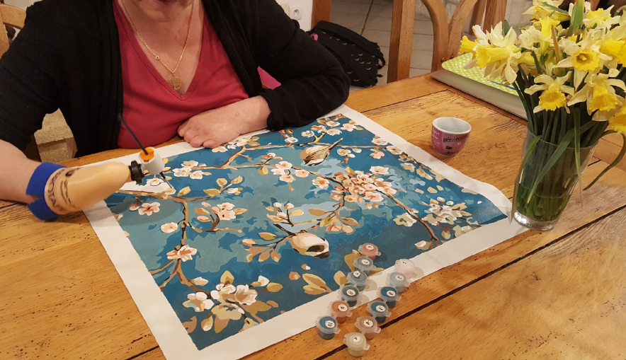
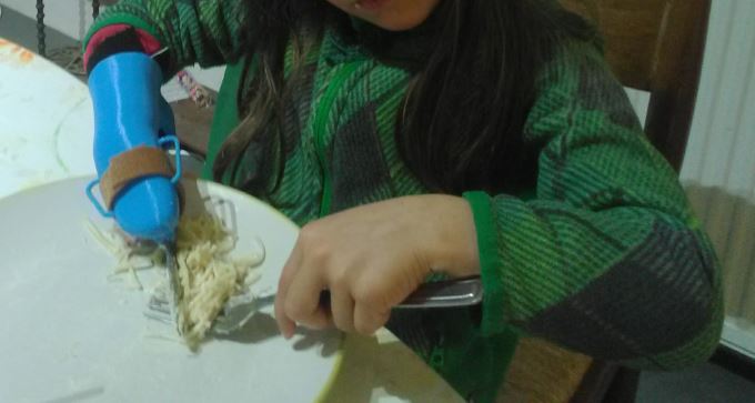
We start using the Equilibras as early as 9 months / one year, i.e. as soon as sitting is possible and handling begins to develop.
Arms being supported allows the child to discover the possibilities of his body, to experience new things that would be impossible without support, while remaining in control of the movement without the help of the adult. As a result, they develop the ability to move their shoulder and elbow, can play longer without tiring and, later on, can carry out these movements sometimes without the help of the support.
These experiences are multiplied in sessions and now at home, thanks to the Equilibras that families can acquire.
Children are quick to realize the benefits, and naturally use the Equilibras as a natural accessory for playing at height. In this way, they become familiar with compensatory tools from a very early age, and can use it to eat or approach their face.
For us, Equilibras is a astonishing tool:
-
- to help children’s motor development,
- rehabilitation: gaining and maintaining joint amplitude, muscle strength and upper-limb function,
- adaptations for activities of daily living,
- prevention of disorders linked to natural compensations that the child would have developed without this tool. (e.g. overloading of the spine).
We are working to scientifically demonstrate its benefits.
Thanks to the entire team Gre-Nable for developing, manufacturing and making available to families this awesome device, which has quickly become indispensable to us!
Helping children play is such a wonderful achievement !
Distribution of Equilibras
Reminder
All projects designed by the Gre-nable team respect the ‘Open Source’ concept as defined by Creative Commons (CC), a non-profit association whose aim is to offer a legal alternative to people (or associations) wishing to free their creations from the standard intellectual property rights of their country.
Following the rules of the Creative Commons license, team Gre-nable authorizes replication, modification and redistribution of Equilibras according to the same criteria of sharing and attribution (BY and SA). Given the charitable nature of our actions and devices feliveries, any commercial use is prohibited (NC).
The Equilibras license is rated as follows: CC-BY-NC-SA. ![]()
Manufacturing file
The manufacturing file is documented in the wiki of our association LOGre : https://wiki.logre.eu/index.php/Equilibras.
Given the technical nature of some of the parts to be milled on a machine tool (CNC), and the attention required for adjustong the settings, we strongly advise you to contact team Gre-nable via the website’s contact form. The team welcomes all inquiries and will support any manufacturing initiative (world-wide).
Warning
- Manufacturing without modification does not require CAD knowledge, but if modifications are envisioned, it is strongly recommended to learn and master the use of OnShape CAD software, available free of charge to makers. Registrate for free account at: www.onshape.com. Numerous training videos are available on Youtube platform,
- Some of the parts used are made of plywood and machined using a CNC milling machine, while others are laser-cut. These machines are generally available from Fablabs,
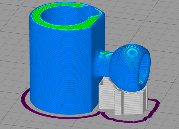
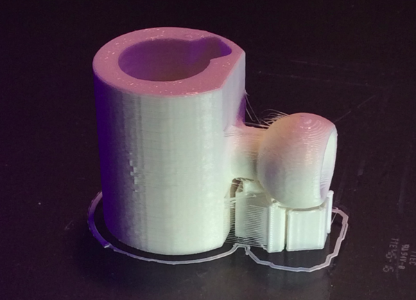
- Other parts are printed in PLA (FDM-type 3D printers also available from Fablabs),
- It’s important to team up with an occupational therapist to use Equilibras, or to train parents in its use.
Happy hack !
(translation using Deepl.com)

Arthrogryposis defined by ChatGPT:
Arthrogryposis, also known as “arthrogryposis multiplex congenita”, is a pathology characterized by stiff joints and limited mobility in several parts of the body. It results from abnormal muscle and joint development during pregnancy.
People with arthrogryposis often experience joint contractures, muscle weakness and bone deformities. Limbs may be flexed or extended, and the severity of symptoms may vary from person to person.
Although there is no definitive cure, treatments such as physiotherapy, orthopedics and, in some cases, surgery can help improve mobility and quality of life.
Like a wink, chatGPT knows the term “Equilibras” and defines it as follows:
Equilibras is a method that combines rehabilitation and re-education techniques, often used to improve balance, coordination and muscle strength. Although there is no single definition, this approach can incorporate elements of physiotherapy, stabilization exercises and functional training.
This is entirely consistent with the aim of our Equilibras


 This work (
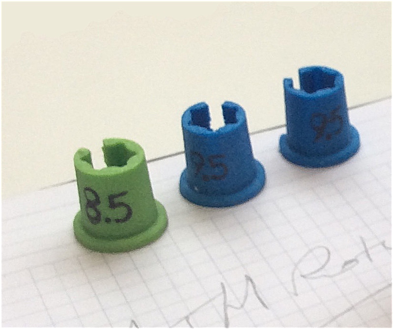
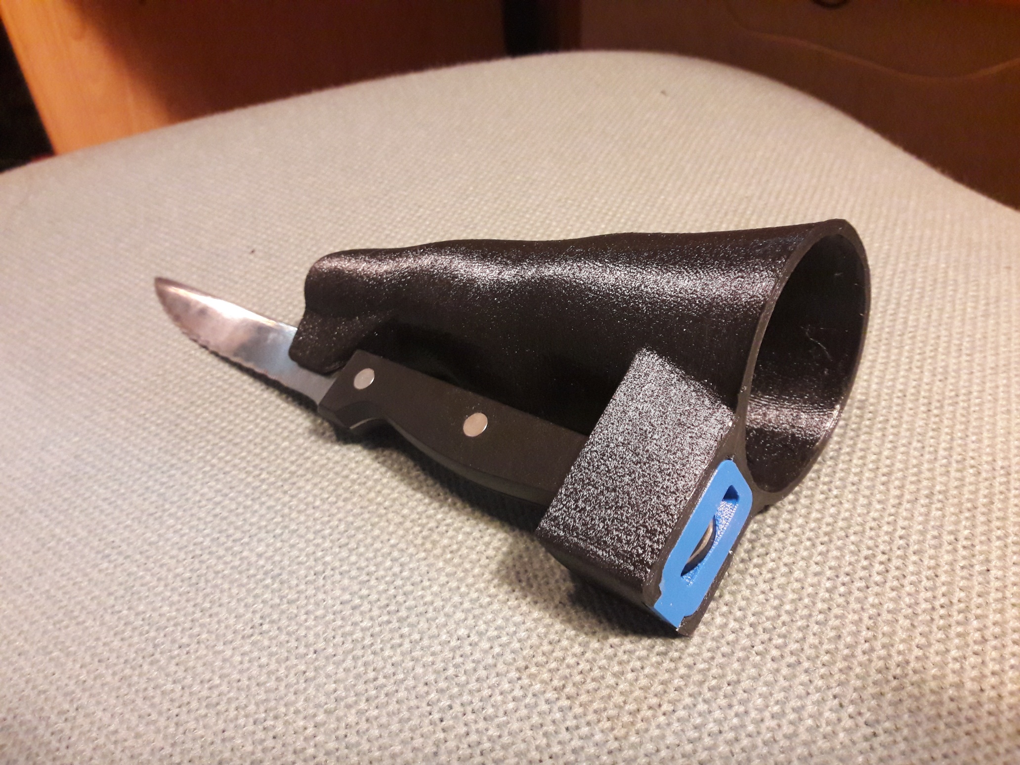
 for the grip: can be coverred with PlastiDip.")


Recent Comments