Team Gre-Nable is keen to present a project done by a group of students from INP Grenoble collaborating with members of our team. team Gre-nable has the ability to promote and use the outcomes of the study to answer all needs required by E-Nable members.
This post is an excerpt of the project’s final report presented by the students for their diploma and is available here in pdf format.
Intro
As part of the product development project our team [the students’ group] is working on the design of a device that helps a young child [Noé] riding his bike. He doesn’t have a fully functioning hand, which makes this a difficult task for him to perform. Our team needs to design a functional final prototype to help Noé ride a bike, which includes testing and prototyping in real conditions to ensure the safety and reliability of the final product.
Our team is tasked with developing this system for Noé because he does not have any fingers on his right hand, which makes him unable to ride a bike accordingly due to his inability to grip the handlebar. The project took place over the course of one academic year and we are currently at the final phase, which is the validation and verification of the final prototype. The group has been working with APF France handicap, an association dedicated to helping handicapped people and children like Noé, who also work in collaboration with Gre-nable, local E-nable members that specialize in creating functional prosthetics. The group has also been working in collaboration with two engineering school teachers Philippe and Marie-Laure [who are members of team Gre-nable].
General Overview
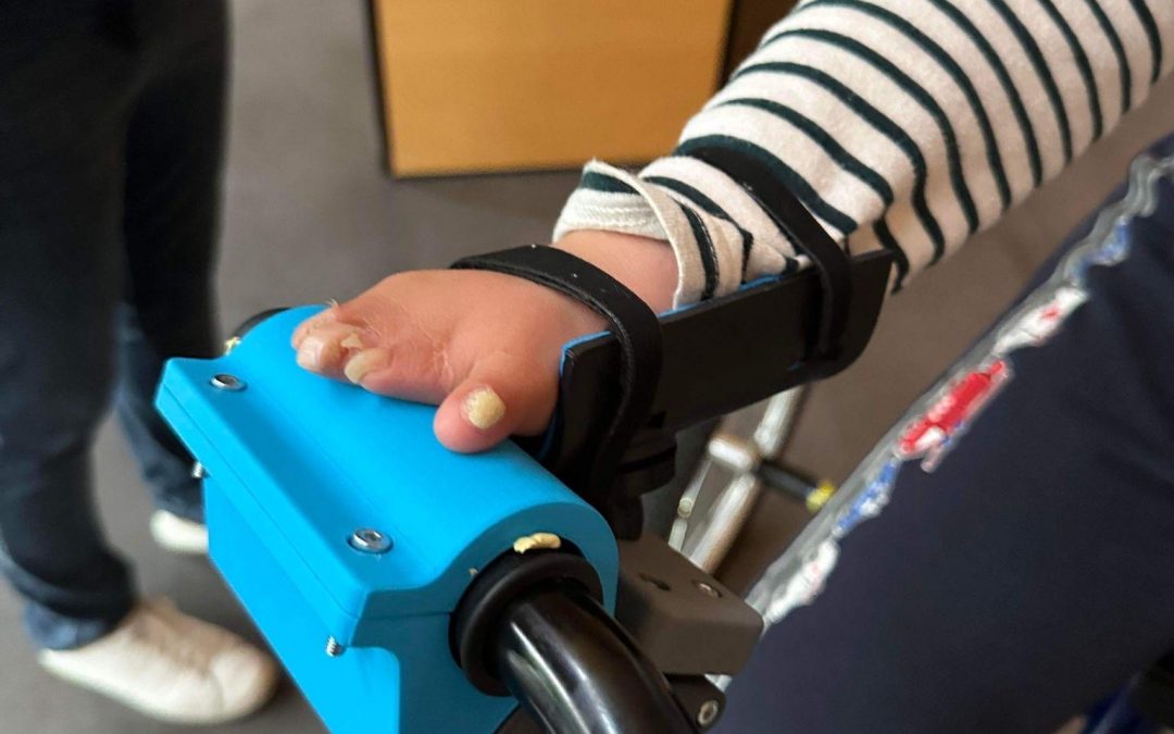
Our project started from a first attempt by the occupational therapist of designing an adaptation for Noé’s handlebar with thermoformed plastic sheets. This deviced proved to really help Noé in biking, but also led to the identifiation of some potential improvements.
Prior to the second meeting with the client, the occupational therapist told us that the main problem with the previous system’s function was Noé’s position and posture while on his bike. His elbow was too high compared to the other arm, creating an imbalance and bad posture resulting in poor alignment of his back. Since the system awkwardly positioned his arm, it was not serving him properly and didn’t have much utility as a consequence.
Another important point we faced was to provide Noé with the ability to move his hand quite freely on the handlebar, even if his wrist is firmly maintained in the socket. This is the reason why we proposed a kinematic made of both a ball joint for free rotation, and a rotary sliding link which made it possible for the wrist to move up and down when cycling on uneven path. The analysis of this kinematics is shown on the picture below.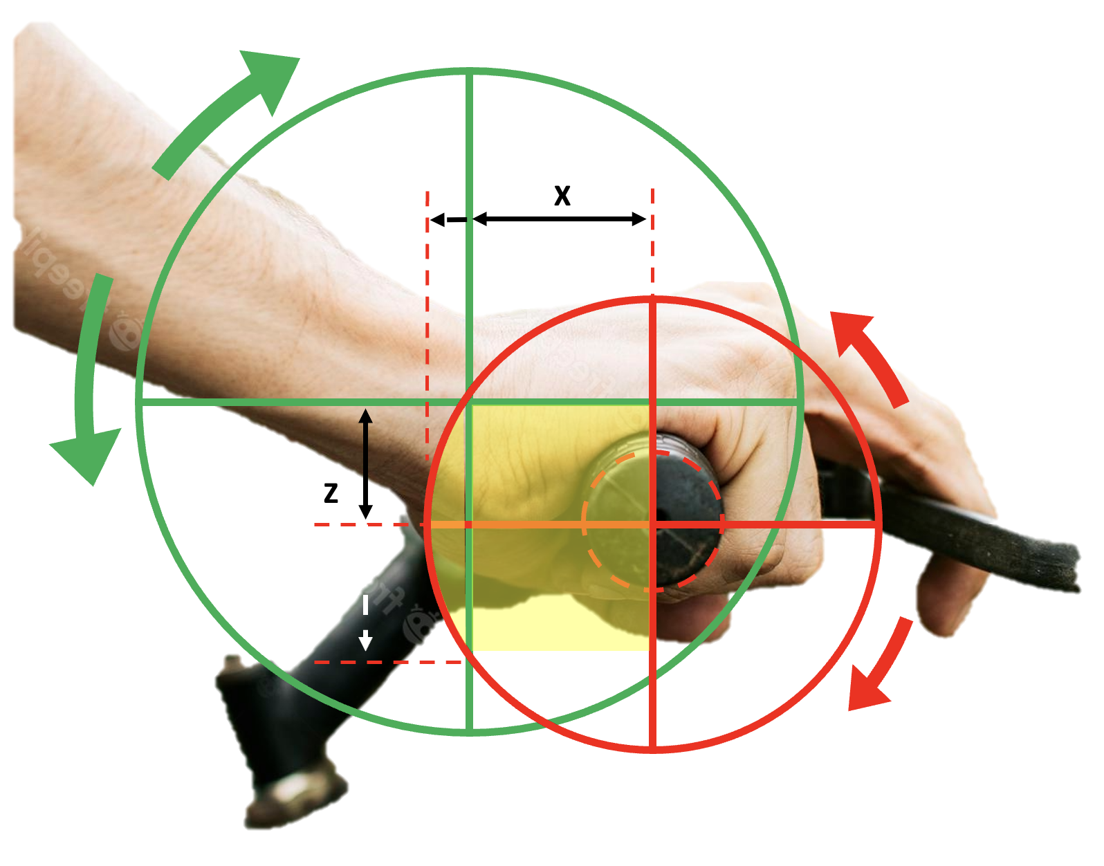
On the aesthetic side, it was also necessary to reduce the size of the system, principally the hand rest or plank, and the system housing as they were visually bulky and not very discreet for Noé’s preferences. In the end, though, we were able to correct the size and form of the final system to achieve a much better, working prototype, which is more adapted for Noé’s helbow and his back posture. Our system’s shape ended up resembling the shape of a duck, which is where inspiration for the name came from.
An overview of the new system should be briefly introduced prior to talking about the new functions and features. As we can see in figure below, the system has been modeled showing the new system in blue, mounted to a rough estimation of Noé’s handlebar. The device is simply slid over the righthandlebar and tightened using two screws to prevent it from slipping off or rotating.

For a closer look at each component we can reference in the image below.
The system features a plank with a ball in the middle, where Noé attaches his wrist when that part of the system is configured to his arm. This piece is able to move up and down via two guide arms (or rails) that slide within the larger housing component attached directly to the handlebars.
Our first prototype featured a stopper in the form of a pin that was installed through the bottom of the rails to prevent the rails and the plank from sliding up and out of the housing once installed, but new components were added to accomplish this in a more discrete way. Instead, internal stoppers were added along the tracks in the housing (shown in orange below). The L-shape of these stoppers catches on the new C-shape of the guides so that when the plank and guides are at their maximum height, they are not able to slide out of the housing. Not only did this save material, but it also removed some unnecessary clunkiness and potentially sharp or pointy aspects from the design that could have posed a safety issue.
The shape of both components were also strategically designed to hold springs on both sides at the same interface in this region, stacked on top of each other, where the design was then able to be more easily reduced in size.
The interaction of these components can be more clearly seen in next figure, where it will be discussed in detail.

Another set of new components includes covers on the sides of the housing, which is shown as transparent in both figures to more clearly see how the system has been redesigned. One purpose of the covers on both the left and right sides is to contain the guides, stoppers, and springs from moving during operation. Another aspect of designing these covers came out of necessity, since inserting the guides and stoppers would make it very difficult to install the springs in any other way. If one imagines installing the guides attached to the plank and then the stoppers, it would be challenging to compress the springs
enough to install them from the top of the housing.
The covers allow the user to first install each component from the sides of the system, where they can then all be nicely encased in a way that they will not escape during operation. At the same time, the springs have a much harder time accidentally coming out or becoming dislodged while riding. Figure below provides a side view of the system that makes it easier to visualize this concept (and it should be noted that the handlebar in both images is not shown to make the images less crowded). This image of DUCK also highlights how the movement of the rails work in this version.
Once everything is in place, the covers retain the components in conjunction with the stoppers, where the L and C-shaped features of the stoppers and guides create a retention point at the location in the dashed yellow box.
Again, this is how the plank and guides are free to move up and down with help from the spring, but do not become dislodged during use. To better imagine the movement, a black double-sided arrow is shown at the bottom of the guide rail. This is how the new design was able to reduce its size and become more sleek, which we will discuss in the next section.

Ball Joint Coupling – Tests and Experimentations
The ball joint coupling is the primary connection point between the bike and the rider.
These two parts, the ball and the socket, allows the rider to easily disengage with the system in case of a fall. It is therefore very important to size it properly in order to ensure the security of Noé. To reduce the lever arm, which provides better solidity and more stability for Noé, we changed our ball joint coupling system slightly. Instead of having more mobility in the socket, the ball will be the soft piece that can deform and enable more movement. The socket can now be integrated in a bigger part, saving space and materials. The socket is now completely solid, printed in ABS and does not have any mobility (completely rigid). Due to these changes it was necessary to size the system properly for Noé, so we then developed an experiment plan.

Several parameters have an influence on the force needed to separate both parts when
engaged, so we will call this force the “release force”. The radius of the ball and the socket
were made to the same dimensions to ensure good mobility.

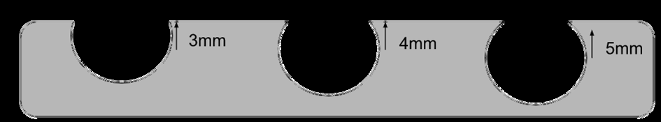
Socket depth : Changing the depth of the socket will make the ball harder to remove, and because the system is round, making it deeper will allow more plastic to wrap around the ball, which will need to be squeezed more to be released. We need to have at least the depth of half a sphere (14.1mm), or its radius, to have a release force (and for retention, too). For better comprehension, we will say for example that a socket offset of 3mm from the surface has a depth of 14.1 + 3 = 17.1mm. Please see section view with 3 sample depths (3, 4, 5mm) for better understanding.
Softness of the ball : To change the softness, we changed the infill percentage when 3D printing this component. We could have changed the interior geometry of the balls but changing the infill % allows us to keep a resilient structure for the piece, and this makes it easier to classify the different balls after printing.
Materials used : Changing the materials for 3D printing will change the properties of the materials and how they influence the system. For the socket, we chose not to change it and keep it as ABS V2 (from Zortrax company) because we needed a solid piece. Having this piece made of a single material makes testing simpler, too. The ball is printed in SemiFlex, and there are different types of SemiFlex usable in GI-Nova such as: Ninja Cheetah and Zortrax SemiFlex.
There are more parameters that could influence the release force, such as the friction between both parts, the form of the system (not perfectly round) etc… But we chose to do our experiment plan on those parameters because we thought they were the main ones with the largest consequences on the release force.


Improvements
Although the project in the end was successful in providing a useful product for our client, there are some points that could have been improved upon. For example, the design changes in version two of the system were well executed but could have been adapted for more adjustability. More specifically, the design aspect with regard to the adjustment of the height of the wrist could have been improved slightly. In the second version, the wrist is situated at nearly the system’s lowest position and is able to move up and down several millimeters. If the position of the L-shape of the stoppers was redesigned so that the point of contact between them and the guides was higher up, the height of the wrist and the amount of movement could be increased. With the covers, offering several different stoppers could make the system more adjustable since these pieces could be swapped and installed relatively easily. However, since the current stoppers worked well for Noé, it was decided to leave the design the way it was.
Considering the second design worked much better than the first and met nearly all of our client’s needs, we can definitely consider the system a success despite the small design improvement opportunities. Nearly all designs and products in general could be improved in some way, even if only to a minimal degree. It is good to recognize and reflect on these improvements for future projects that require similar methodologies, too, especially as our group continues studies in engineering and eventually more professional experiences.
In the end, the team was very satisfied to have met our goals when faced with the challenges presented by this project. Our group managed our time very well, and was able to equally distribute the work throughout the year in a way that made it possible to have a successful outcome. This has proven to be a very interesting subject to work on that taught us valuable lessons and skills that can be taken away and used in our futures, too.
Recent Comments