About licensing
 This work (Electrically Assisted Flexibone Hand) is provided under the terms of License Creative Commons Attribution 4.0 International.
This license concerns the whole related documentation, reports, CAD models, testing videos, etc.
The shape of the hand is based on Kwawu hand designed by Jacquin Buchanan.

This project is Open Source Hardware certified : [OSHW] FR000008
Introduction
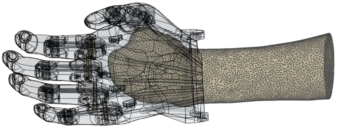
This article presents a novel design for a low-cost, 3D printed, electronically assisted prosthesis for a transmetacarpal amputee. The design is the result of a recent collaboration between students from the University of Bath, England (Phil Barden, Thomas Eagland, Jay Pinion, Sevinç Şişman), and a member of Team Gre-Nable, located at Grenoble Institute of Technology, France (Philippe Marin). The team worked to design the prosthesis over a 5-month period, with the final design being the result of extensive force testing and mechanical analysis, rapid prototyping, and user testing. For a more in depth explanation of the final design and the project, please refer to the full report that providing all details. See at the end of this article for even more links and information, CAD model, Arduino code, video records of the tests, etc.
Much of what is presented here are proofs of concept, and it is our hope that by sharing these ideas with the rest of the e-Nable community, others will be inspired to build and improve upon them. Happy reading!
The mission
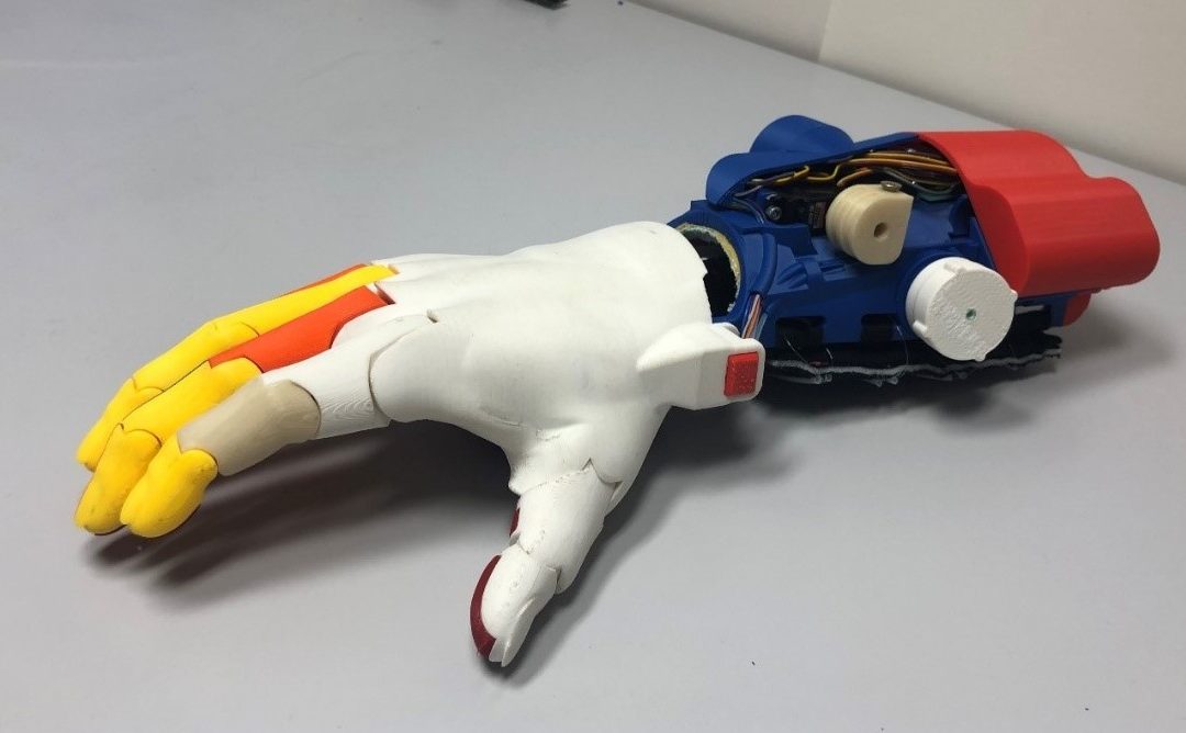
Most of “robotic hands” developed for amputees are designed with actuator motors integrated inside the palm, like this prototype we have seen on “makea.org”:
“your mission…”, Philippe said to the team, “is to design an electrically assisted prosthetic hand – I mean with motors, battery, mechanics… – for a lady who lost ‘only’ her fingers. This means there is no room in the palm to put all this stuff”.
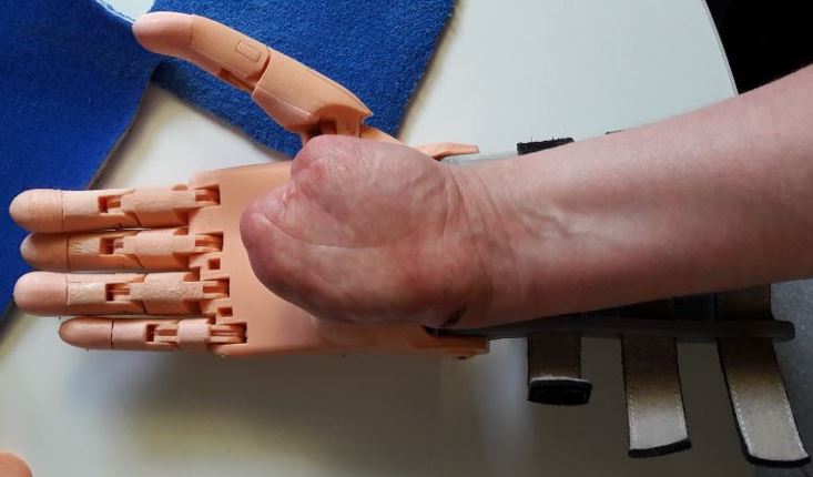
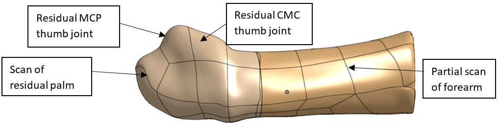
Nathalie’s residual hand
Background of the case
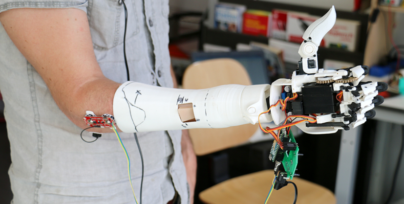
The project focused on a lady called Nathalie, a transmetacarpal amputee who approached team Gre-Nable back in 2018 saying she was unhappy with her €48,000 myoelectric prosthesis and asked whether the team could help designing a better alternative for her.
Her primary complaints were that it was far too heavy (weighting approximately 1.5kg, almost three times that of a human hand), and very difficult to control. The prosthesis consequently sat unused in its box.
The design presented below weighs approximately 500g, which is very close to that of a human hand. The approximate cost to recreate it is also close to €200, or less than 0.5% of the cost of her myoelectric prosthesis.
I like it more than my €48,000 prosthesis.
The final Prototype features…
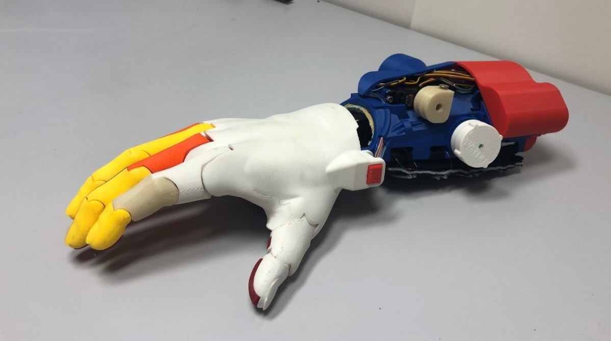
- Force Feedback
- Pressure sensor in index finger
- Haptic motors array in gauntlet
- Attachment Method
- Snowboard binding mechanism
- Power supply
- 7.4V Lithium ion rechargeable battery
- 2200mAh
- Providing several hours autonomy
Most of these elements are described in the following sections…
- Mechanical Design
- Flexibone finger design
- Original fishing wire routing
- ABS & Ninjaflex 3D printed parts
- Actuation
- Two servo motors
- Whipple-tree pulleys
- Controller
- 2 axis Joystick
- Arduino board
Claims
As for a patent description, we claim in this article that, as far as we know, the following elements are innovative in the context of low cost upper limb prosthetics:
- Finger kinematics made of a single flexible printed part that allow inter-phalanges bending, together with soft gripping pads in the fingers.
- Haptic feedback array in the gauntlet made of a series of vibration motors.
- Control by a two-axes joystick taking profit of a residual possible movement of the amputee limb.
- Twistable locking mechanism for attachment of the gauntlet on the forearm.
Features detailed Description
Flexibone Fingers
Description:
A novel finger model designed by team Gre-Nable and based on the Kwawu model, using a design with ‘bones’ passing through the centre of each finger and thumb, printed using a flexible 3D polymer called NinjaFlex. The bones are then covered by ABS shells representing the phalanx which give each finger three articulation axes and consistent rigidity. Like usual e-Nable designs (Phoenix hand), fishing wires are used to mimic tendons in all fingers to contract them.
This structure makes the “Flexibone Finger” very easy to manufacture by printing only one simple flexible part, and six rigid half phalanxes (made of ABS or PLA). Moreover, the flexible part realizes two functions:
- the first one is making three pivot joints,
- and the second one is integrating pads for a soft contact, that may be coated with rubber like painting (for example Plasti-DIP).
We believe this new Flexibone Finger concept is a major improvement for creating prosthesis, whatever the final type of hand is concerned. For the time being, our Kwawu based hand will benefit from the concept, in near future other type of hand prosthesis may integrate these Flexibone concept. Team Gre-Nable is in the process of developing a simple parametric standard finger based on the Flexibone concept.
 for the grip: can be coverred with PlastiDip.")

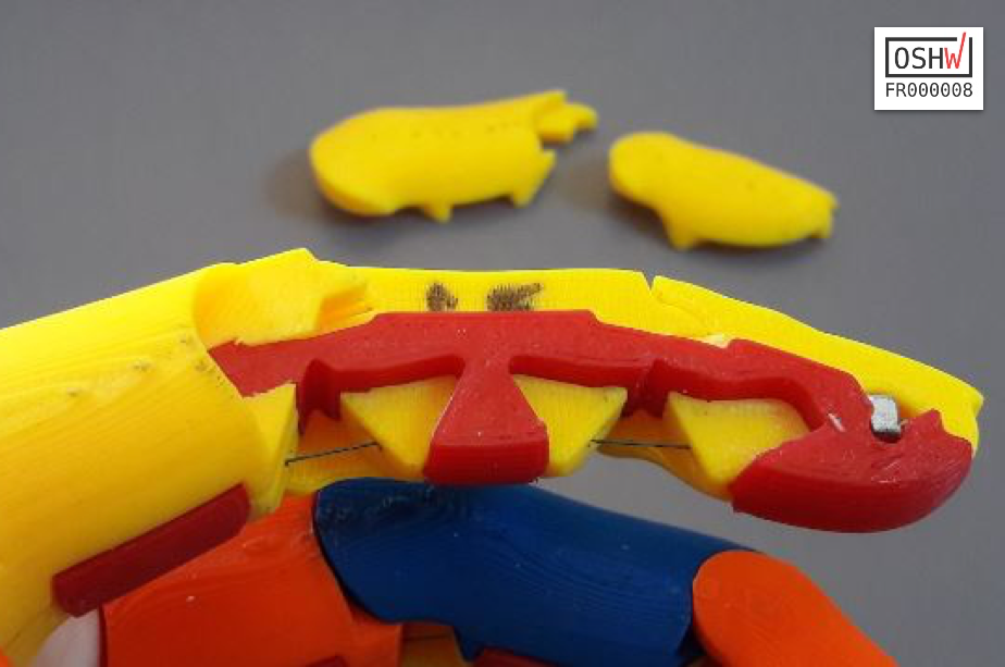
The Flexibone Structure
Testing:
This design was chosen through the means of testing and comparison against other common e-Nable models (namely Kwawu and Phoenix). Two tests were carried out:
- a force test, to find the design that required the least amount of force to fully contract an index finger,
- and a grip test, to find which model could grip the greatest range of objects, analysing both object sizes and maximum weight.
The Flexibone hand came second to the Phoenix hand in the force test, both needing considerably less force to fully contract a finger compared to the previous Kwawu design. However, the Flexibone design performed far better than both the Phoenix and Kwawu designs, with it being able to grip objects both larger and smaller, and objects of a much greater weight.

Test rig with servomotor, pulley, fishing line, force sensor, and sample finger in the vice.

Some of the printed series of parts for various parametric studies during the project.
Explanation:
The design works by having three areas of the bone which are thinner and are not constrained by the ABS plastic shells. The fishing wire runs up the centre of the flexibone, and when a load is applied to the wire, bending occurs at the three weak points hence contracting the finger. Due to the elastic nature of the flexible polymer, when the load is released from the fishing line the fingers return to their natural resting position.
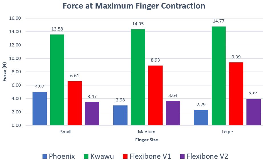
This bar chart shows a sample result of a force test, comparing the maximum force required to completely bend a variety of fingers, for three different sizes (small, medium size and adult size). It appears that despite its very nice and ergonomic configuration the Kwawu requires more force in the tendon lines. On the other side, the Phoenix hand with dental elastics is still very good with this force criteria.
Fishing wire routing
Description
The routes of the fishing wire (that represent tendon lines) travel from the tip of each finger to the actuation system located on the gauntlet. For most of the wrist actuated prosthetic hands, tendon lines pass over the wrist, and this routing strategy generates a direct link between the wrist flexion angle and the fingers bending position. As we don’t work on a wrist actuated but motor actuated solution, we had to separate the wrist movement from the fingers behaviour. The solution is to route the fishing lines through the wrist rotation axis. This allows the user to bend her wrist freely without altering the tension in the fishing wire.
After having tested fingers behavior, we know that the grip efficiency will be improved if the least force is lost between each actuator and its related finger. That is why we also want to minimise friction along the tendon lines. As expressed previously in this post, we felt that the wire routing strategy may have an impact on tendon line friction and we decided to assess the importance of this impact. This led us to make trajectories as smooth as possible, and to pass wires through PTFE pipes.
Testing
Because the tested e-Nable prosthetic hands proved to feature a wide range of force to bend the fingers, and this could be due (among other reasons) to differences in tendons routing strategies, we decided to search for a routing that generates as little friction as possible. Several fishing line routes were tested to find the increase in contraction force due to friction, depending on the angle of the curves along the route (see figure below). Additionally, the results were compared to see how PTFE tubing affected this force. The test showed that if the route is lined with PTFE tubes then the friction force is reduced by half, and that the shallower the curves in the route the smaller the additional friction force.
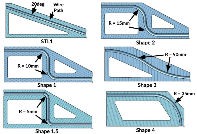
Geometric parameters of tested trajectories for tendon path.
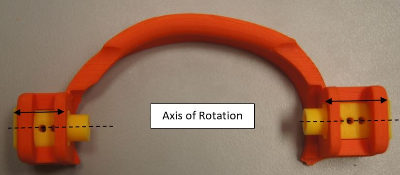
Arch and wrist axis, with tubing holes.
Final tendon path, as smooth as possible, and through PTFE tubings
Explanation
For the fishing line actuation to work while allowing Nathalie to move her wrist, there should be no change in tension of the fishing line, therefore no change in its path length. To achieve this the five routes for the fishing line had to go through the axis of rotation of the wrist as the path length remains constant at this point. The smooth trajectories and PTFE tubing then ensure that the fingers still require a low force to contract as it has a lower coefficient of friction than 3D printed ABS.
Actuation
Description
Two servo motors, each driving a pulley, contract fishing lines that act as tendons in the fingers. The first servo motor drives both the thumb and index finger, and the second drives the remaining three fingers. A whippletree mechanism is built into the pulleys to allow for adaptive grip, as well as tensioner boxes similar to those found in other e-Nable hands.

Pulley CAD model

In case of unbalanced load fishing wire slips on Whippletree.
Explanation
The pulleys are made up of two separate parts, the first being the pulley itself (blue) and the second being the pulley insert (red). Inside the pulley insert a Whippletree is located. The Whippletree allows two of the fingers to be attached to the same piece of fishing line. When one of these fingers is experiencing a greater load acting against it than the other, the imbalance in force causes the fishing wire to slip round the Whippletree, therefore ensuring that other finger can continue to contract without the motor overloading. The pulley insert can also be moved further into the pulley via a tensioner system. As a screw is rotated it pulls the insert into the pulley, therefore increasing the initial tension in the fishing line and tuning the initial position of the fingers.
Controller
Description
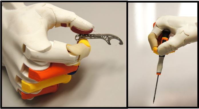
The user controls the prosthesis with their residual thumb joint using a joystick inside the palm.
Sensor types evaluation
After a bibliographic review of sensors classically used for prostheses control and their potential performance, an experimental study of a variety of interfaces have been performed in order to evaluate their usability in the context of this prosthetic hand. The tested sensors were low cost myoelectric sensors, pressure sensors (FSR), and flexion sensors.
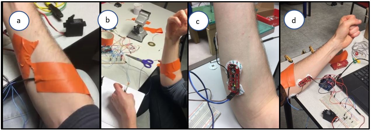
All sensors presented an element of inaccuracy, with the myoelectric sensor being particularly unreliable. This was primarily due to difficulty in finding optimal electrode placement.
After analysing the ergonomic capabilities of the recipient, the team finally converged on the opportunity of making use of the mobility of her residual thumb mobility.
A series of small joysticks have been tested, trying to find one easy enough to manipulate with low movement amplitude, and being also as compact as possible to be integrated in the palm thickness.
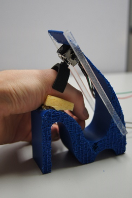
First joystick attachment test rig.
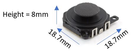
Compact PSP joystick
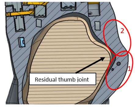
Potential areas to place the joystick
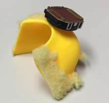
Joystick connected on the palm interface, with sponge foam for elasticity.
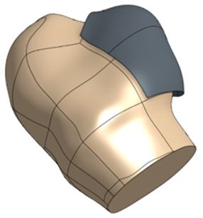
Palm-joystick interface part, by offset of the scanned palm.
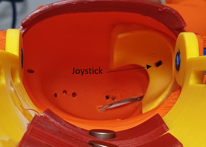
Joystick and interface integrated in the palm.
Finally, a very compact PSP joystick was found, saving space and avoiding too important modifications of the external prosthesis shape. Also sponge has been put in between the attachment and the prosthesis, to avoid unwanted movements and to ensure the joystick returns naturally to its neutral position.
Explanation
Typically, electronically assisted prostheses use myoelectric sensors as a means of control, and this is a proven method that has seen much success in modern prostheses as a controller. Despite this, the users of such prosthetics often report them to be difficult to control and unpredictable. The myoelectric sensors often provide noisy signals that can worsen if sweat gets between the sensor and the users skin. A prosthetist is also usually required to find the optimal sensor locations which can be costly and time consuming. For a controller, predictability and reliability is key.
In the case of this project, the user is a trans-metacarpal amputee who, on her right hand, is missing all her fingers but retained some of her thumb joint. This joint has a large range of motion and is capable of precise movements, making it ideal for a means of control. To interface as closely as possible with the user’s central nervous system and to therefore implement an accurate controller, the team decided that utilising this joint would be preferable over myoelectric means or other types of sensors.
The joystick controller was successfully used throughout testing with Nathalie using a basic open-close or ‘bang-bang’ configuration. Moving the joystick towards the palm (abduction) closed the fingers, and away from the palm (adduction) opened them. It was proposed that variable speed could also be implemented, as well as being able to turn the system on and off and toggle between grip patterns, although sadly there was not time for this to be implemented or tested properly. A joystick is a very versatile tool that can be used as a complex controller and has been used as one for decades in devices like video game controllers. It’s therefore highly likely that, with training, a user could learn to give more complex commands to the prosthesis.
Force Feedback
Description
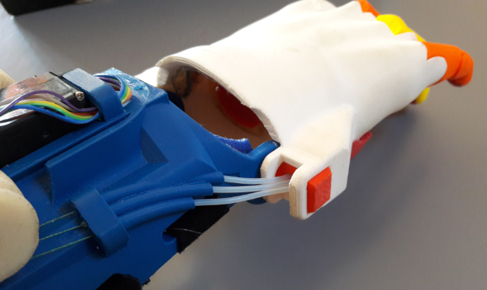
A pressure sensor in the index fingertip indicates to the user the grip force being applied to an object by vibrating one of four haptic motors in the gauntlet. The pressure sensor is entirely concealed within the NinjaFlex fingerbone. The haptic motors vibrate on the surface of the user’s forearm, with a different motor vibrating depending on the force applied through the fingertip. The motor closest to the hand vibrates upon contact with an object, and the vibration moves further up the forearm as the force increases.
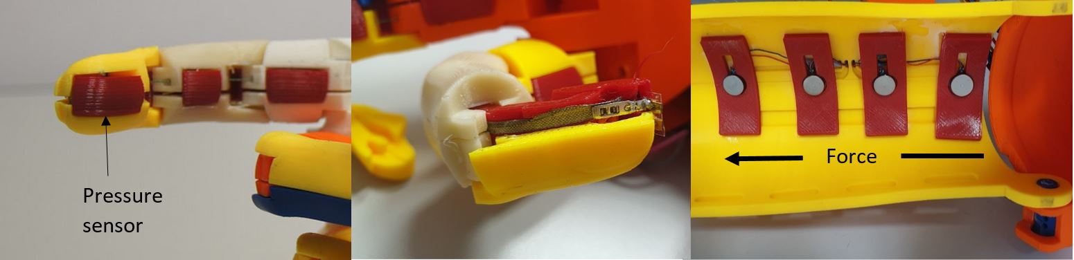
Left: Index finger and sensor location. Middle: partially disassembled index finger showing the conductive fabric route leading to the pressure sensor in the fingertip. Right: Haptic array in the gauntlet made up of four vibration motors.
Explanation
Researchers have found that implementation of force feedback is of great use to an individual in terms of improving embodiment of a prosthesis and improving performance when grasping, particularly for delicate objects. The implementation of force feedback was therefore explored in this project using low cost materials. Conductive fabric was used in lieu of wire to avoid the wire fatigue that would inevitably occur in the finger under repeated flexion and extension. Although not done so here, pressure sensor(s) could also interface with the actuators using the Arduino as a means of closed-loop feedback (i.e. limiting the maximum force that can be applied to an object).
Attachment on the forearm
Description
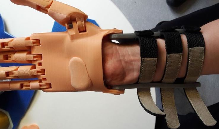
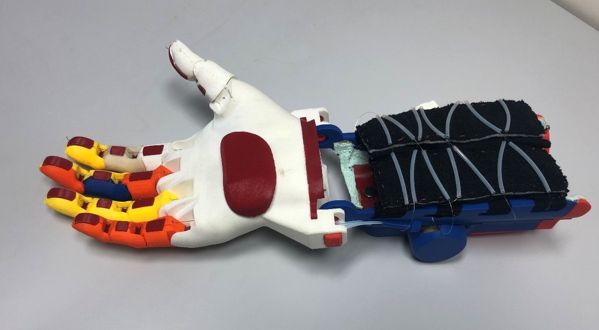
In place of a usual Velcro straps or similar, a more comfortable option has been investigated by the use of soft fabric that is tightened by a fishing wire and a locking mechanism inspired by BOA Fit system (often used for snowboard boots) and its use by Younes Zitouni in the e-nable.fr community.

Parts of the twistable locking mechanism
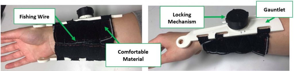
Comfortable gauntlet tightening mechanism
Test
In order to assess the maintaining potential of the solution, the wire strength was tested up to breaking force. Also different routings were tried, and it was seen that a double helix (cross hatched method) routing was a better option to have a uniform tightening and distribution of the load, together with the easiest releasing process. Several types of fabric were compared to converge to “Tissus3D” which provides a comfortable feeling to the user, and, in addition, is often used by prosthesists for skin interface.
Explanation
Based on the binding of a snowboard boot, this fastens the prosthesis to the user in a similar way to a shoe lace. This method was developed due to the user being unsatisfied with the Velcro straps on her existing prosthesis.
Optimizing finger configuration
Description
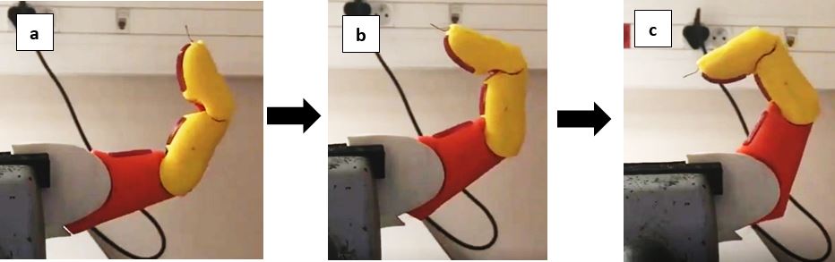
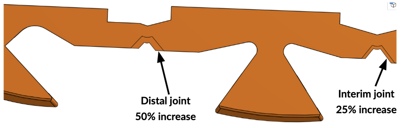
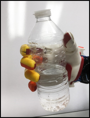
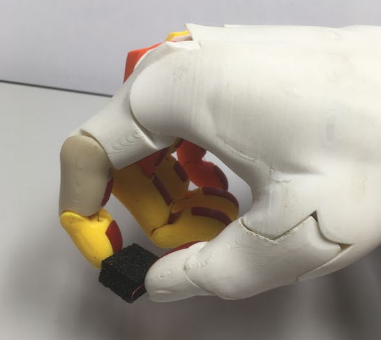
It appeared during tests with Nathalie that she was often not able to grasp a bottle with our prototype. This was due to fingers contracting so that the distal joint rotated fully before the intermediate and proximal joints began to bend. This led to the distal bone making perpendicular contact as seen in figure Figure 16‑11, followed by the object being pushed away from the palm. To allow the prosthetic to grip the objects, a more natural order of contraction needed to be achieved.
Test
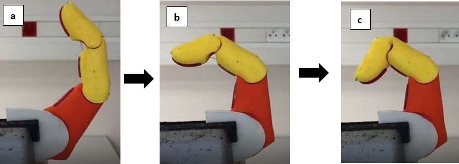
Below is compared on the first line of images the bending process of the original Flexibone finger, and on the second line the bending process of the final one.
Explanation
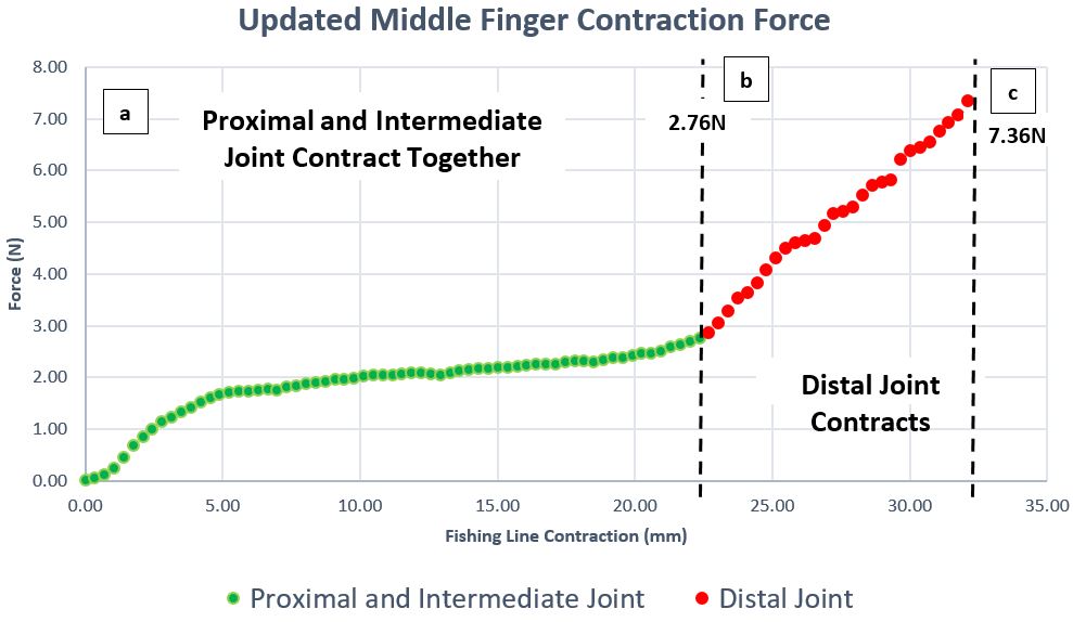
After a series of tests, this issue was solved by increasing the thickness of interim and distal flexible joints in the bone, by 25% and 50% respectively (see figure below). A drawback is that it increases the force needed to completely bend the finger (see curve below). Due to time constraints, a final global decrease of thicknesses in all three joints has not been investigated.
Grip patterns
Description
Thanks to the Arduino code and the two-axis joystick, several functionalities have been implemented. And others could be developed if needed. The main grip patterns are described on the following figures: finger point grip, power grip, two-point tip pinch, lateral grip.

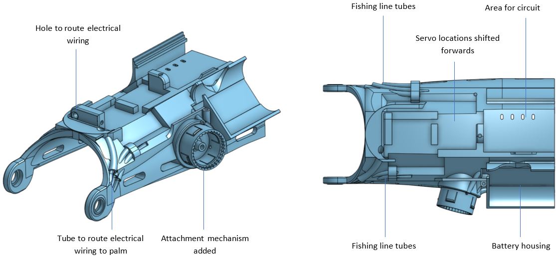
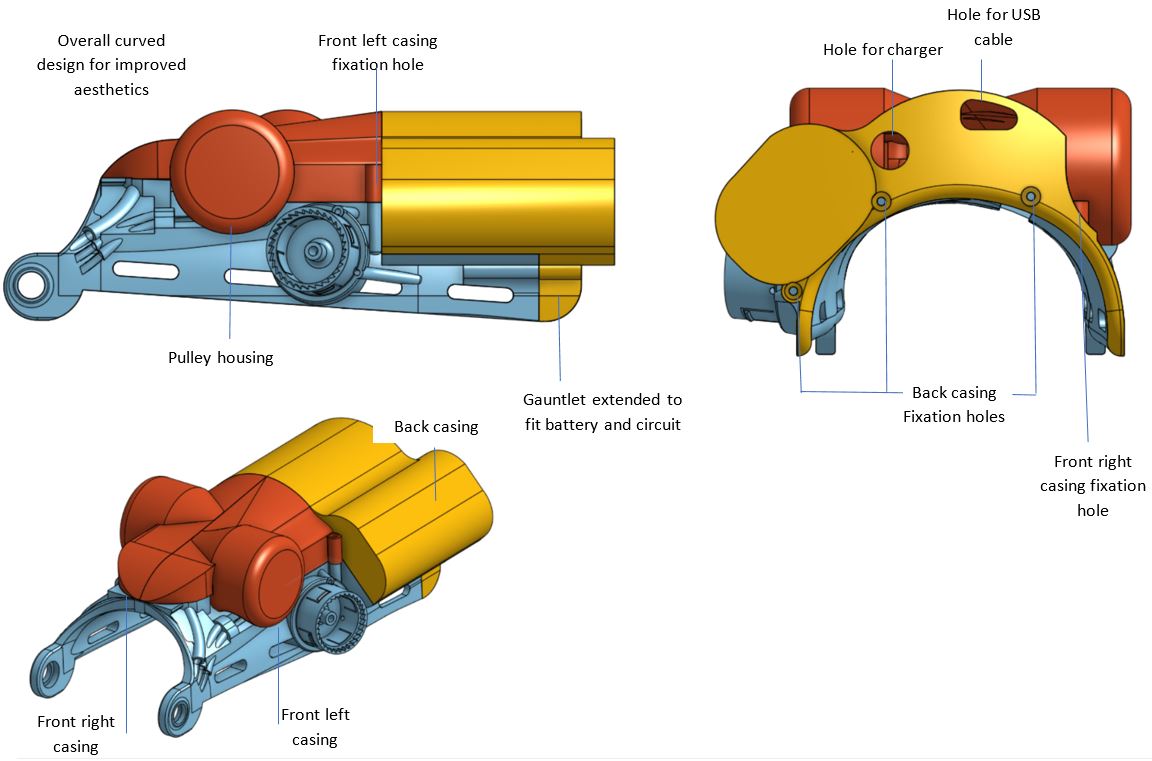
Final Gauntlet
Here is a summary of the final gauntlet layout and casing.
Potential improvements
Among many ideas to improve technical or functional aspects of the Flexibone assisted hand, here are the main priorities:
- Thumb rotation plane: The orientation we made for the thumb does not really allow opposition with the forefinger (see power grip image above), which makes it difficult to grap some objects. Maybe we did not put the same way as the original Kwawu… This plane could be slightly modified, and the thumb movement amplitude also increased.
- Haptic feedback : The position of the pressure sensor in the forefinger tip does not act always the same way depending on the contact configuration with the object. Could we find a better configuration, or a different sensor, so that the contact force would be properly detected in most situations? Also which haptic motors is activated seems difficult to figure out by the user. She says she feels vibration in the gauntlet but she feels difficult to know on which location.Reducing the contraction force of the fingers
- Reducing the contraction force of the fingers. To improve finger contraction strategy we increased some of the Flexibone joints thicknesses, which finally increased the bending force that the fishing line has to provide. The drawback is that the greater the force that is lost through the tendons, friction, and bending of the fingers, the lower the force that remains for gripping objects. We should now investigate the possibility to decrease the flexion force by decreasing all joint thicknesses, keeping the relative flexion order and of course keeping a reasonable mechanical strength of the fingers.
A full open source project
Not only this article, but all data generated along this project is released as the open source “Flexibone Assisted Hand” under a licence Creative Commons Attribution (CC By). We are happy to provide the community worldwide with:
- The full report (
 )that describes details about how the project went on, and all explanations about testing experiments and results, and all technical choices and justifications
 - The CAD model is available in an Onshape public workspace. You just need an Onshape free account to access it. Feel free to consult and if you want, to copy the workspace in order to edit, modify, improve… and if so please provide your improvements to the community! We will be more than happy if you give us feedback
- And other data that you may consult, from “A to Z”:
- A – our Log Books
- B – Electronic Development Arduino code
- C1 – video Designer Testing
- C2 – video Electronic Testing
- C3 – video Second Interview
- C4 – video Final Interview, two-fingers grip only
- D – Force Sensor Calibration
- E – Test Rig Assembly Guide
- F – Force Test Code
- G1 – Force Test Results
- G2 – Force Test Video Results – Flexi V1
- G3 – Force Test Video Results – Flexi V2
- G4 – Force Test Video Results – Kwawu
- G5 – Force Test Video Results – Phoenix
- H – Grip Test Code
- I.0 – Grip Test Results.xlsx
- I.1 – Pictures Grip Test Results
- I.2 – Videos1 Grip Test Results
- I.3 – Videos2 Grip Test Results
- J – Friction Test Procedure
- K – Friction Test Results
- L – Mechanical Feedback Development
- M – Motor Comparison Table
- O – Core 6V 400 Motor Data Sheet
- P – Motor Driver Comparison
- Q – Attachment Method Force Test
- R – Attachment Method FEA Analysis
- S.1 – Finger Joint Force Test Results
- S.2 – Finger Joint Force Test Results Videos
- T – Gauntlet and Casing Dimensions Drawings
- U – Final Arduino Code
- V – Motorised Attachment Method Improvment Code
- W – Total Costing Breakdown
- X – Onshape CAD Link
- Y – Locking mechanism solidworks
- Z – Assisted_Flexibone_hand_2019_Project_Report
- Finally, if you just want to print the parts and build a copy of this, you can find STL files on Thingiverse
- We will appreciate if you follow any works on the project with comments.
Acknowledgement
Thanks to the team Gre-Nable Philippe, Patrick, Fabien, Marie-Laure, for allowing us to work on this amazing project.
Thanks to Frédéric for his coaching in project management.
Thanks to all the Team of GINOVA, the University Fablab in Grenoble Institute of Technology for his technical support during this project.
Thanks to Patrick also for his help in publishing this article on the Team Gre-Nable blog.
And of course, many thanks to Nathalie (and her family) for her confidence in our work, and for being available for several tests along the project.

During the final meeting, from left to right: Tom, Phil, Nathalie, Sevinç, Jay.
Bonsour Medames/Messieurs,
Thank you for your open-sourced Ratchet clamping system (on Thingiverse.com).
I found your work because of the ratchet dial system.
My name is Sangho Yi from Mand.ro Co. Ltd. in Korea, and we make affordable robotic prosthetic devices since in January 2015.
– Youtube: https://www.youtube.com/channel/UCjG2dC5NV17K2EWCANMGAMg
– Mand.ro Web: http://mand.ro
Hope to have a chance to collaborate with your group in the near future.
Cordialement,
Sangho
This is brilliant and wonderful work. It needs wider dissemination.
Happy New Year!
Hi Jon,
Yes, I think the Flexibone concept is really promising and we will continue working on its improvement. And the work done by the UK team on the electric hand is also a significant step in the direction of low cost assisted hands.
Obviously new ideas from this basis are always welcome also: Thank you for helping dissemination of our propositions within the e-Nable community, and especially advertising through the entry point on the hub https://hub.e-nable.org/s/team-gre-nablefr/ .
Best regards and happy new year to the whole community!
Philippe