Terminal Socket for Keyboard Typing & Smartphone Use
Open source project:
This design, like all those made by Team Gre-Nable, is open source. We explain in these articles why and how they were done, the reasons for our technical choices like the means and tools we used. All 3D models are available under the Onshape environment (free access for public models). This design is accessible on Onshape by using the Search tool with team Gre-Nable.fr : manchon Jean“.
Jean’s Situation …
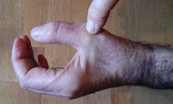
Jean is an adult suffering from agenesis of the right arm. He has his elbow and forearm only 9cm long, with very conical form and ending with a small “bud” … he has become accustomed to use among others to typing his MacBook’s. And we must admit that it is impressive with his “dexterity”. But the more and more intensive use of his computer for his work ends up hurting him and generating pain from his little “finger”. He would like to protect his skin while maintaining his dexterity he has acquired in the usage of the keyboard. He has already consulted two or three professionals who made him special appliances, which ultimately did not suit him. He then contacts Team Gre-Nable.
Molding & Casting
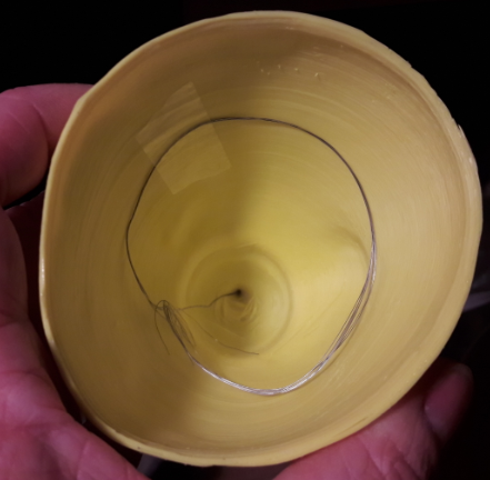
An alginate molding session provides a plaster model of Jean’s forearm and elbow. Note on the image below many bubbles that have been trapped in the hair of his arm during molding, which generates these small “balls” distributed on the surface of the plaster model. These were removed very easily with a cutter blade on the plaster. We can distinguish very well in the upper part the “bud finger” Jean used until now to type on the keyboard of his computer. In the lower part of this molding, the slight restriction of section is due to the presence of an elastic band we place intendely to clearly mark the location of his elbow during molding. This restriction will be removed (smoothed) between the 3D scanning operation and the CAD volume reconstruction.
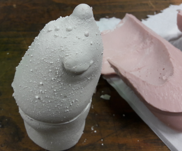
Plaster model cast from the alginate mold.
Comparison of 2 brand/types of 3D scanners.
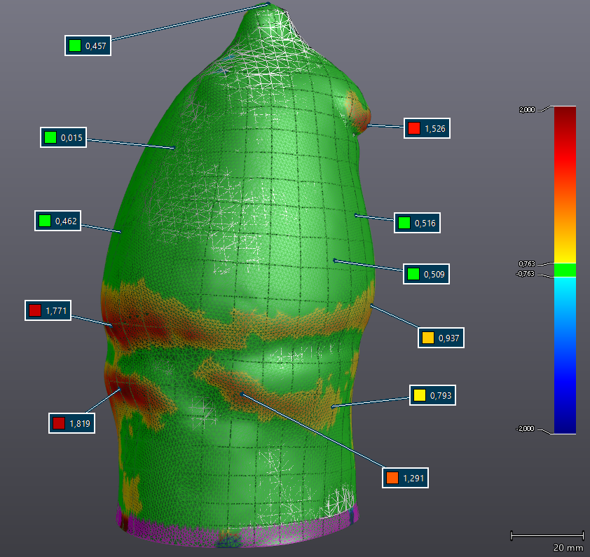
This plaster model is digitized with a 3D scanner. We took this opportunity to compare the iSense (see also https://3dscanexpert.com/structure-sensor-review-part-1/) with a high-end HandyScan 700 professional scanner. HandyScan 700 .
The Handyscan will be considered as the reference tool, with a reported accuracy well below 0.05mm on this type of object.
Results of scan shows the iSense giving efficient results for this application (accuracy less than 0.7mm, average around 0.5mm) in most areas with few variation of curvature, however, in more rugged areas, errors can reach nearly 2mm. But since we foresee the insertion of a comfort glove with thickness of 3mm (blue 3D fabric visible on the featured image near the Jean’s elbow: the process of designing this comfort glove is fully described in his post), and that we can also count on the adaptability of the flesh in contact with the socket, it seems that the quality of the iSense will be sufficient to digitize this model in plaster.
Please note that a direct digitization of the arm would probably have generated larger dimensional variations. We will keep the accurate scan made with the Handyscan as we have it.
A CAD model will be created based on this 3D scanning (obviously a mesh file), and exported in STEP format for use by Onshape online webapp.
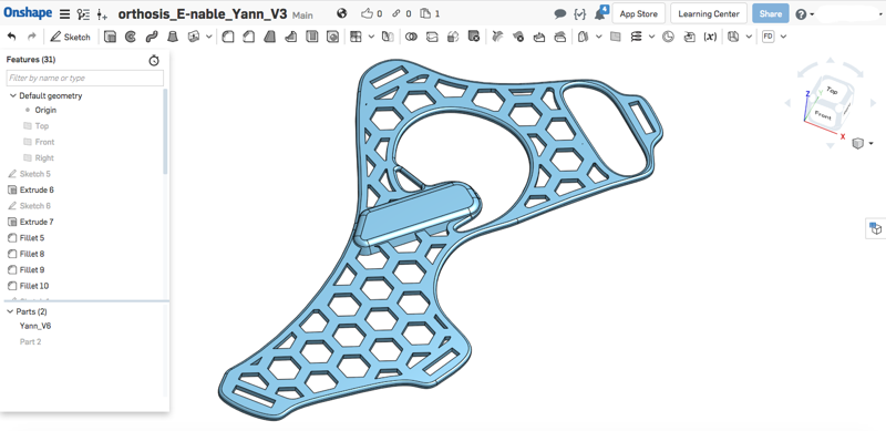
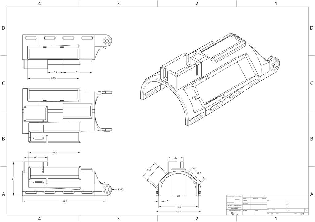
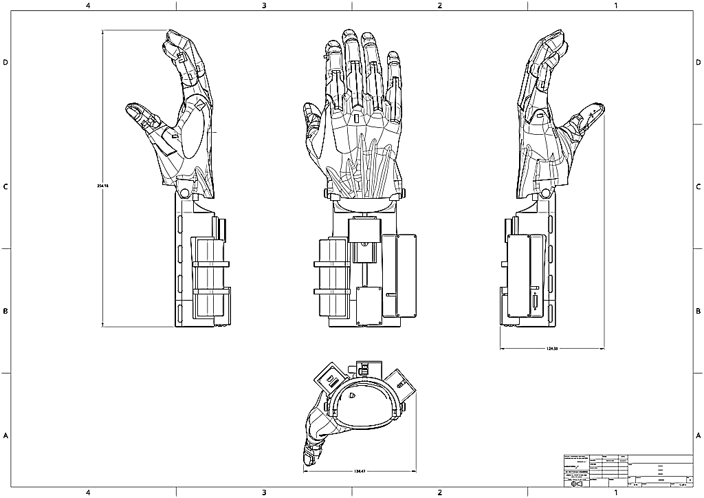
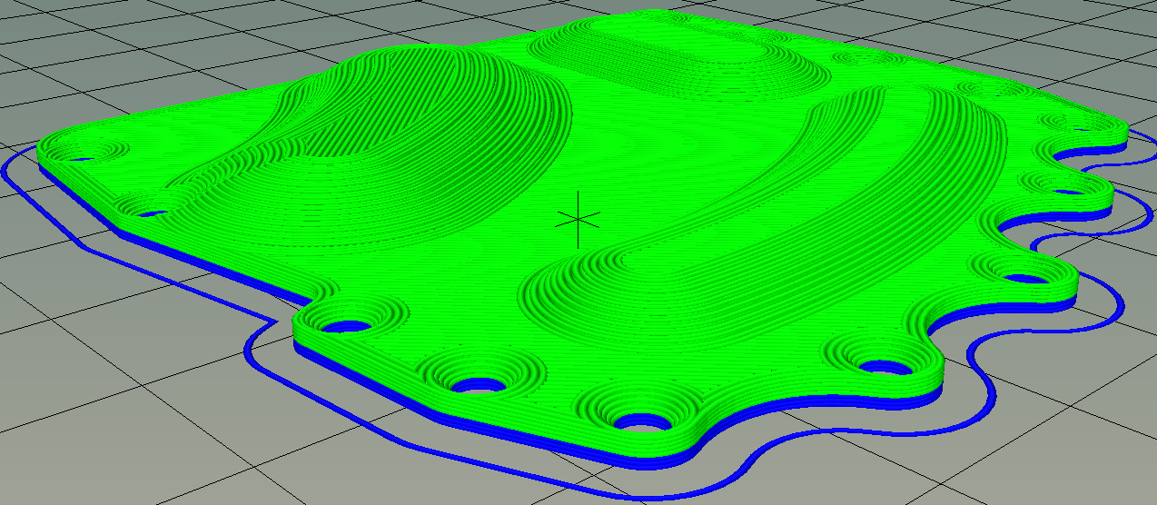
Socket Design
Two new models are generated thanks to VXelements application (associated app with Handyscan scanner of Creaform)), with offsets of surfaces of 3mm then of 5mm. We wanted to test these features in VXelements (and we were very satisfied with the results) nevertheless these surface offsets and the generation of the new volumes could have been done with other modeling tools, either on the STL model (with Meshmixer for example) , or on the reconstructed STEP model (Fusion360, Onshape, etc …). You can read our post “Création d’un Multi-tool holder“for an example of using the “Surface Offset” function in Onshape.
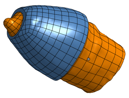
The three volume models obtained, which we will call “ arm “, “ arm + 3 ” and “arm + 5” are imported into Onshape in STEP format. A boolean (volum) subtraction operation between “arm + 3” and “arm + 5” makes it possible to obtain a socket with a thickness of 2 mm thick, 3 mm away from the arm.
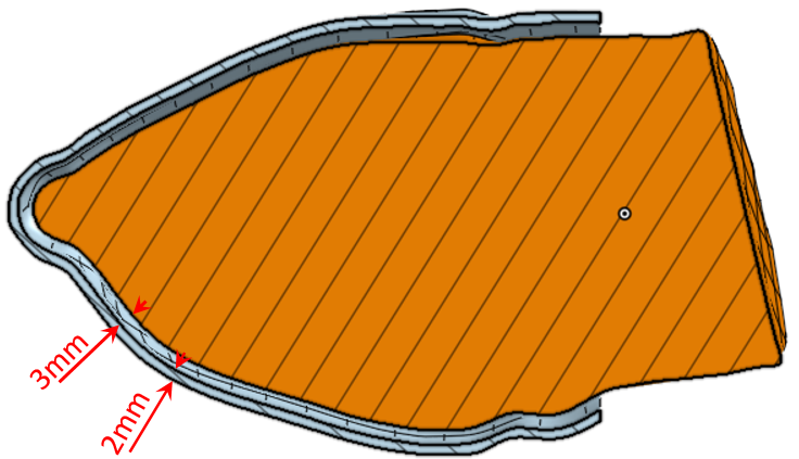
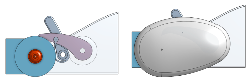
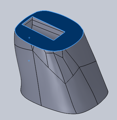
ARM and initial socket
Clearance around pinky
An additional offset of the surface, followed by some cuts and re-assemblies of volumes allow us at this stage to release a significant clearance at the end of socket, which will avoid the contact between the Jean’s finger and the socket. This protection is the main element of his design “specifications” transmitted to us, so we pay special care for this!
Then we add an artificial “finger”, which will be equipped with a flexible tip ( made of NinjaFlex) to allow a soft touch with keyboard’s keys.
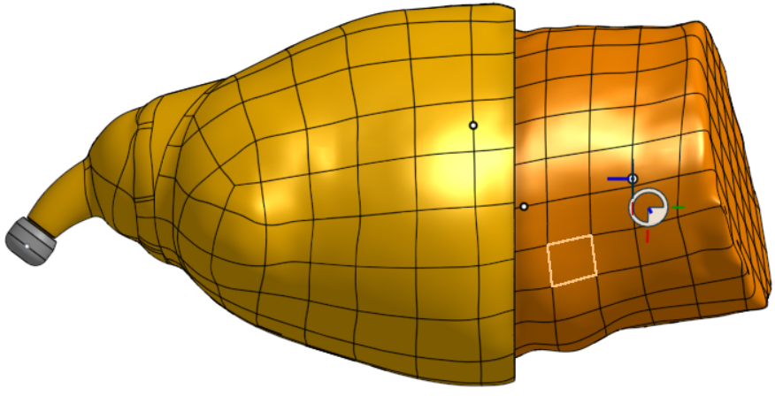
Socket and finger, external view.
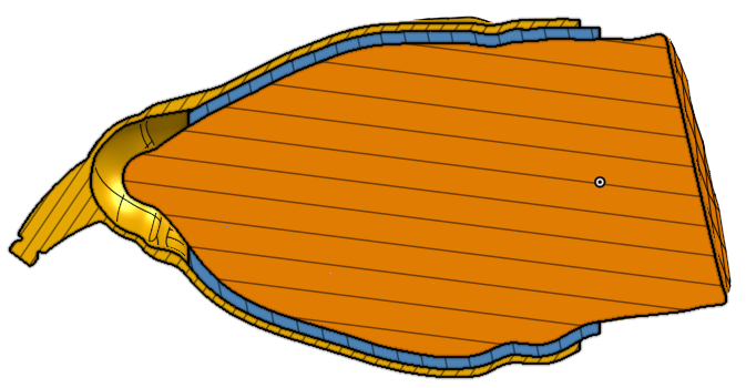
Preparing 3D fabric, and clearance provided around Jean’s bud to prevent any injury.
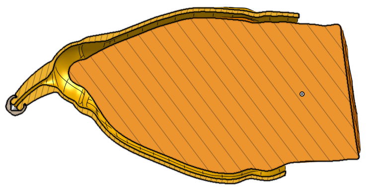
Socket and finger, section view on.
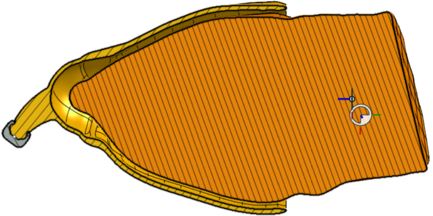
3D fabric : finger clearance.
Adaptation for touch screen
Like most of us Jean uses a smartphone or tablet and thus a touch screen.Could he take advantage of this artificial finger to manipulate the apps on this type of screen ?
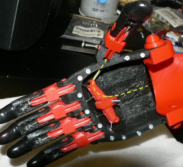
I had studied this issue few months ago, and I came to the conclusion that it should be possible. Indeed most of the current touch screens are capacitive, and speaking without too technical terms (which I would not control for that matter!) the touch screen detects a variation of potential generated by a slight leak of electrons when the finger touches the sensitive surface. It “would be enough” therefore that the end of our plastic finger (in this case the foam cap) would be connected to a sufficient electrical mass to provoke a slight electrically discharge during contact with the screen. The solution is …
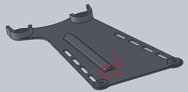
- drilling a small channel inside the artificial finger to insert a flexible electrical wire,
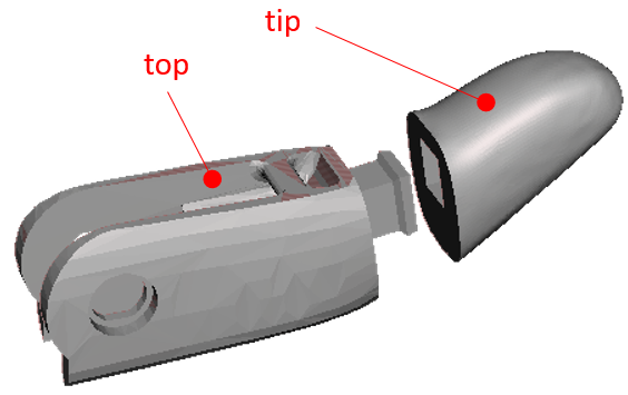
- to replace the current printed tip (made of Ninjaflex) with an conductive tip retrieved from a smartphone stylus,
- and to connect the wire to a metal mass, and possibly touching the skin of the user.
Channel to end of the tip for the wire

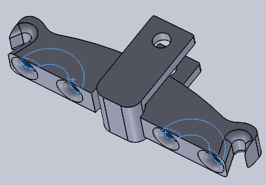
Wire exiting toward conducting tip
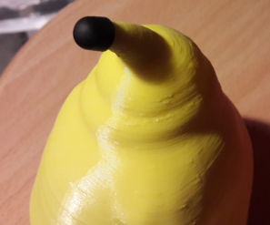
Former stylus tip placed on the finger
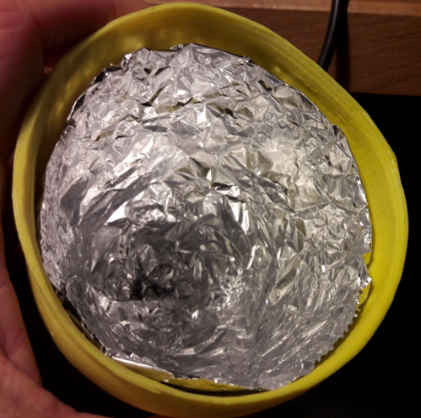
Electric mass made of aluminium foil (kitchen product)
Electric wire as an alternate solution
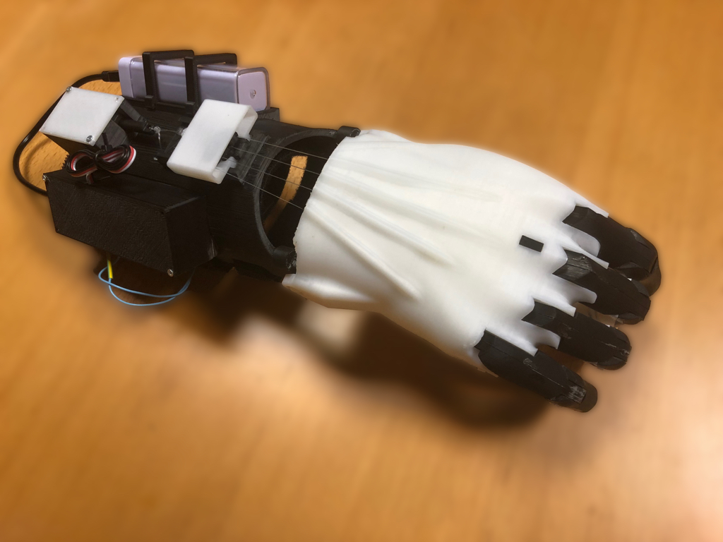
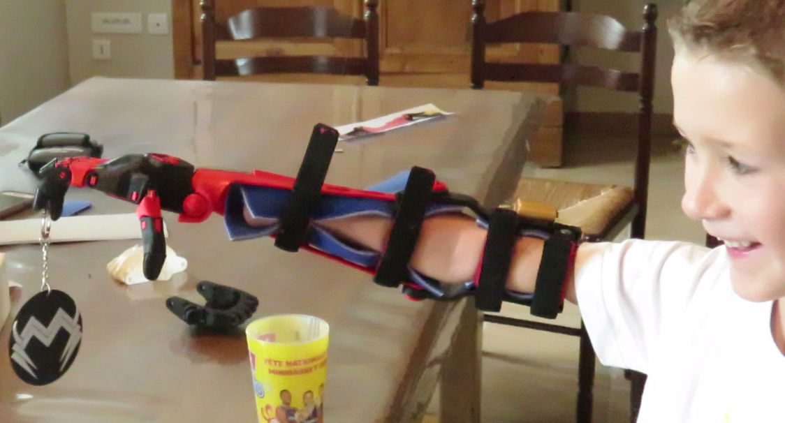
Results of first tests
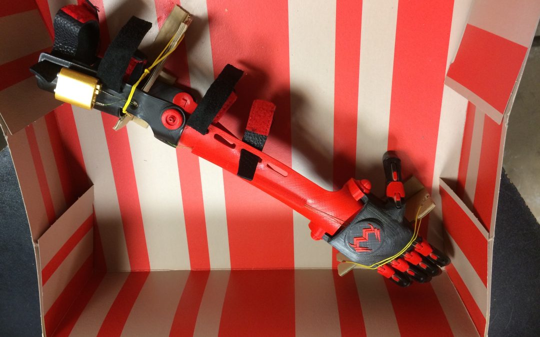
The second meeting with Jean (after the molding) was really satisfying.
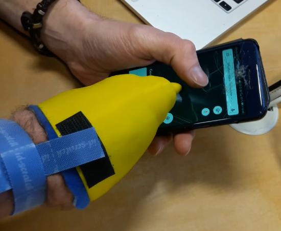
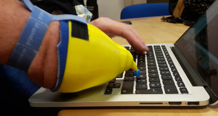
remaining point was to imagine a way to maintain the socket well in place around his forearm. The first tests were done by placing two pieces of adhesive Velcro on the edge of the socket, and placing another strip of Velcro around his arm. The following videos taken during the first minute of use in each context (keyboard and touch screen) show that Jean will undoubtedly succeed in appropriating this new tool … if it is already done from this moment.
Very first try, Jean typing on his Mac.
Jean’s first test on his touch screen. See how smoothly he zooms with his left thumb and right “index”!
Holding the socket on the arm
The very conical shape of the Jean’s forearm does not allow effective hold by simply clamping in this area. The first tests showed the feasibility of maintaining a strap around the arm, but we are looking for a solution that would be easier to handle, and that would avoid a localized tightening certainly not comfortable.
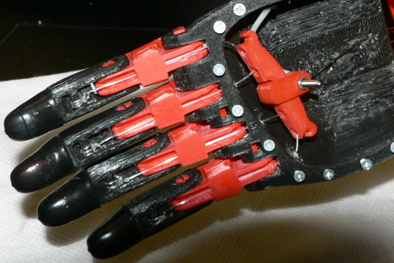
It seems then that the proposal made by Dominick Scalise to use a fabric sleeve for some prostheses would fit here.
A first test is done by cutting a sock … it seems to work well, and we propose to Jean, by email, to test himself this solution with the socket it uses.
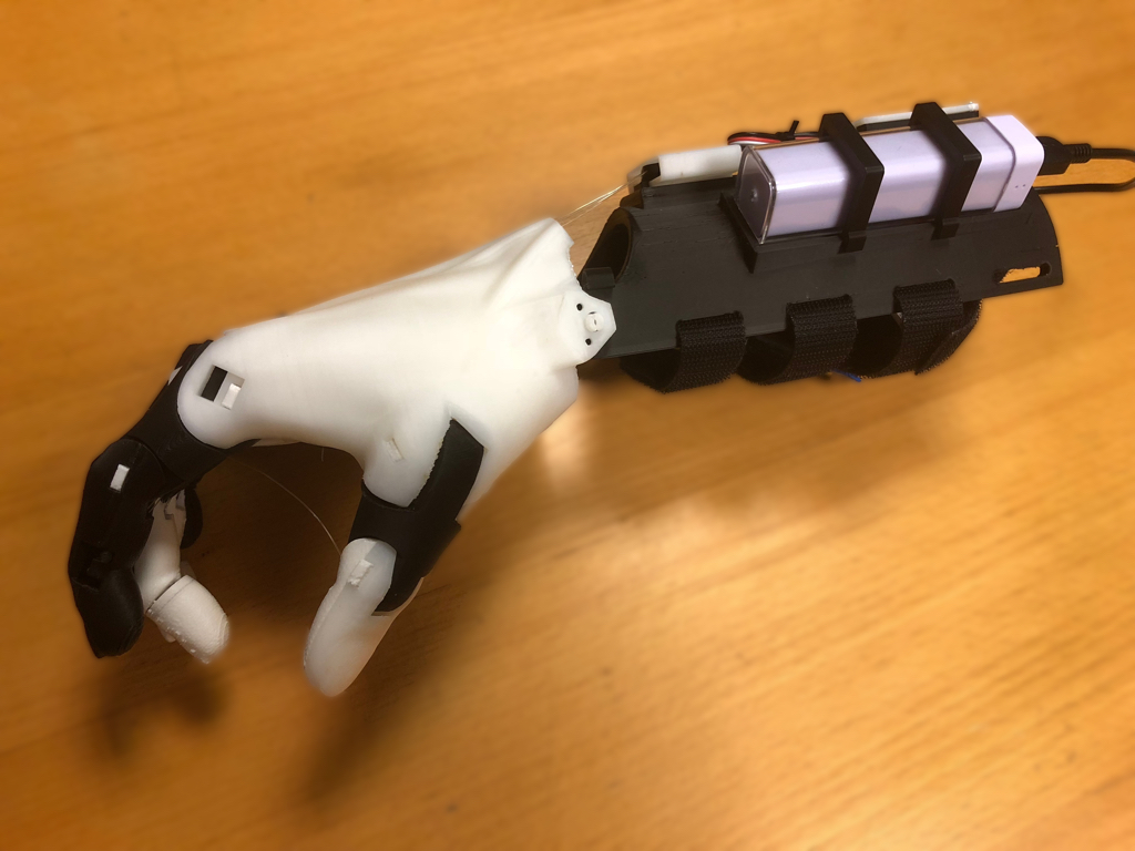
Meanwhile, we also offer a socket version printed in TPU (semi-flexible material) rather than PLA, to further improve comfort. Let’s not forget that John wants to use this device every day for several hours.
In our third meeting, Jean introduced us to the fixation solution he found : he replaced the idea of the sock with an ankle (usually used in the case of a sprain) that provides homogeneous and very efficient clamping. Just find the right dimension, and he will use or not the complementary elastic straps that come with it.
The TPU version seems to seduce him on the comfort side, and he plans to reduce the length, or even cut a slot on the side … what we do on the spot.
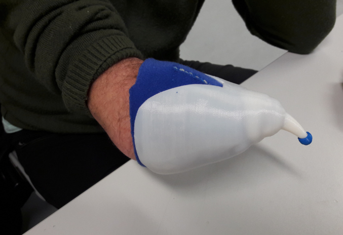
Printed release with TPU with slots. Please note the “glove” made of 3D fabric.
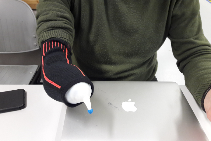
Hold with ankle (it may be necessary to use the size below)


Recent Comments