Select Page
Ski pole

Ski pole

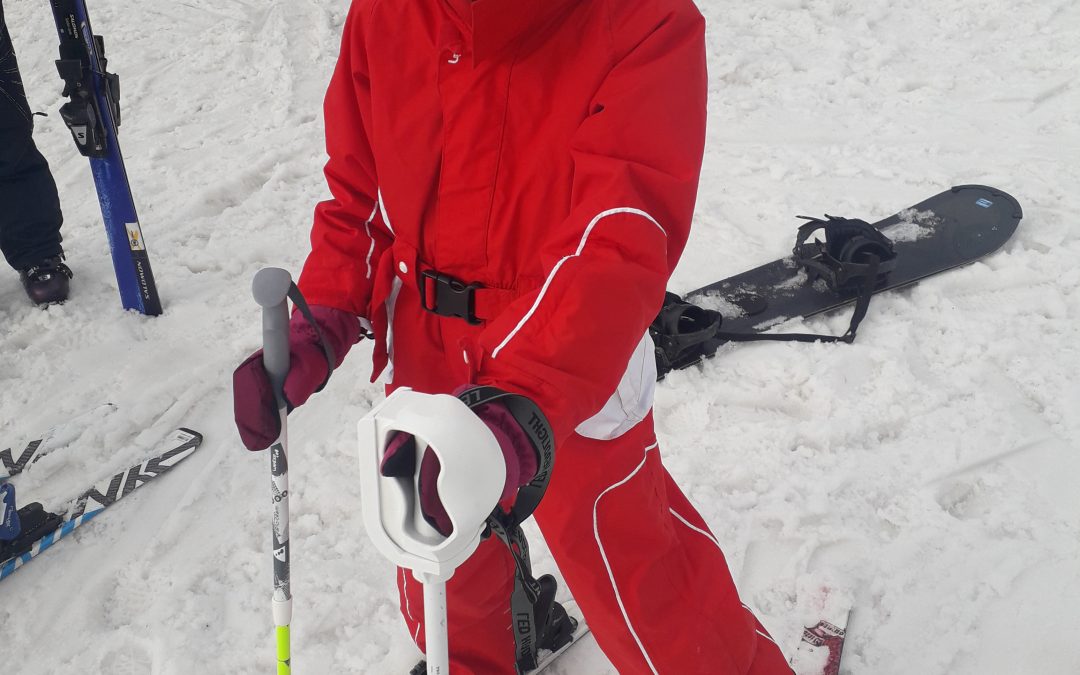
Manon, hope for the 2030 Olympics ?

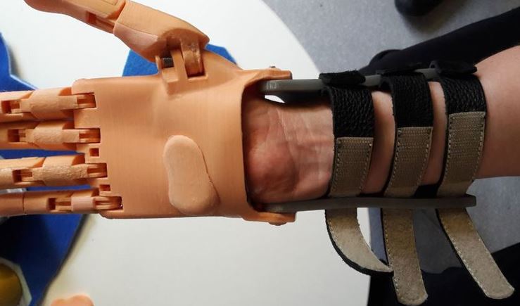
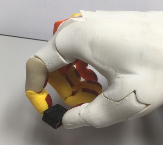
Our previous design of the ski pole aimed at Pierre-Luc, based on the principle of ball joint that enclosed his palm, does not seem appropriate to us in Manon’s case, because her clamp function can be performed by his thumb and his pinky. Of course the strength of this clamp is clearly not sufficient to hold a ski pole, so we keep the principle of using a socket build around her hand.

We therefore define new specifications intending the left hand palm to have the same feelings of touch as her right hand.

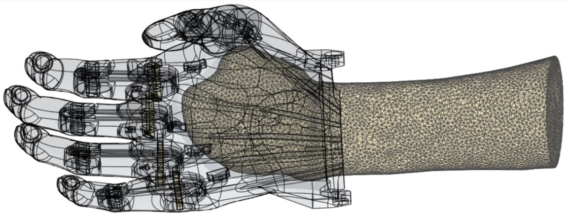
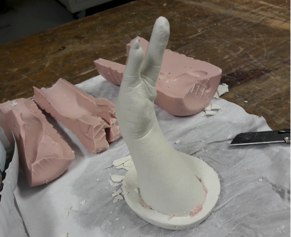
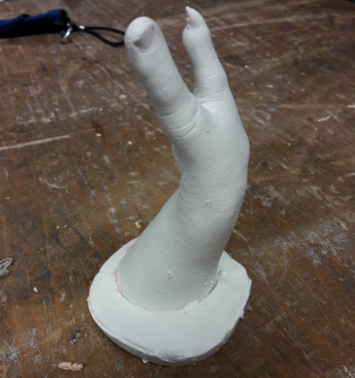
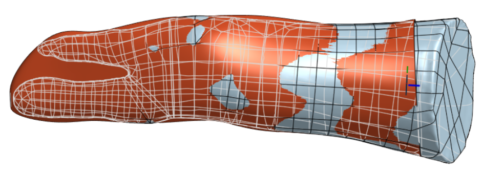
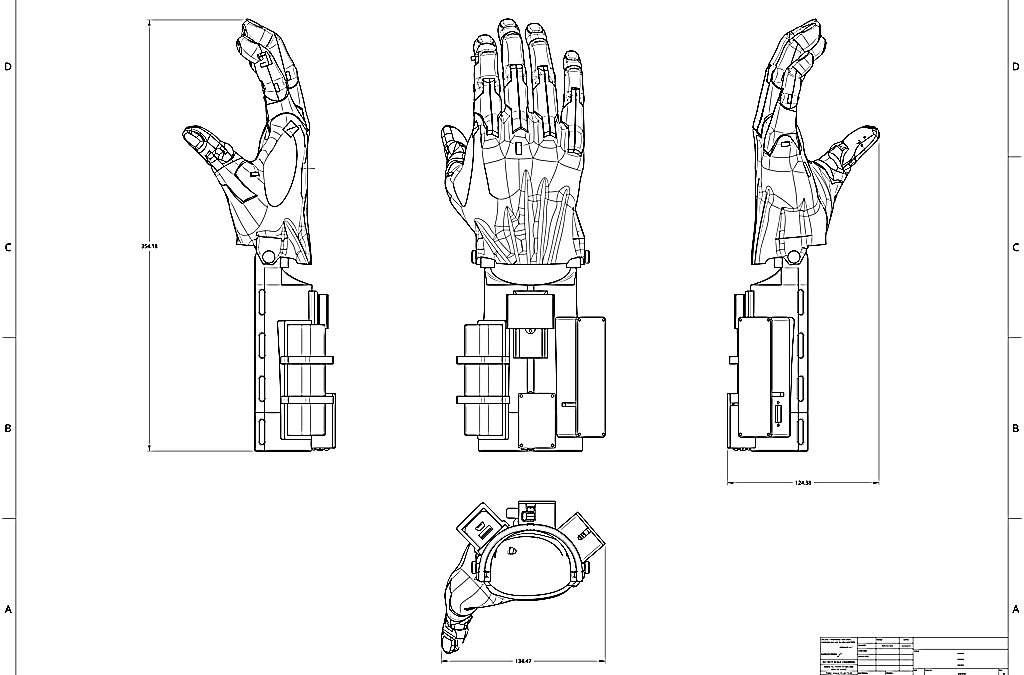
Scan of the left hand, equipped with a muffle

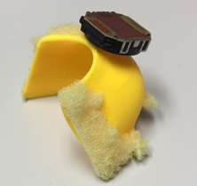
Pour ce nouveau projet, nous essayons de nous passer de l’étape moulage, en réalisant un scan de la main in-situ, en position de maintien du bâton de ski. La main étant équipée d’une moufle qui sera ensuite bien adaptée par la couturière de la famille.

For this new project, we are trying to work without the molding stage, by performing an in-situ live hand scan, right in the position of holding the ski pole. The hand being equipped with a muffle which will then be well adapted by her family’s seamstress (grand’ma).

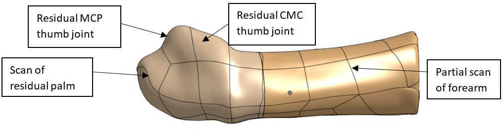
The scanning operation is not as easy as expected, but after 3 attempts we got a good quality mesh file.


Another evolution of our process, we will not transform the resulting mesh (STL format) into a B-rep file for importing into our usual CAD software (Onshape).

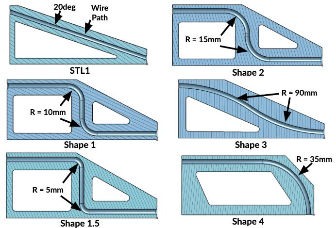
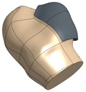
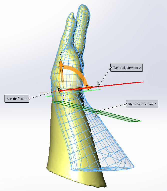
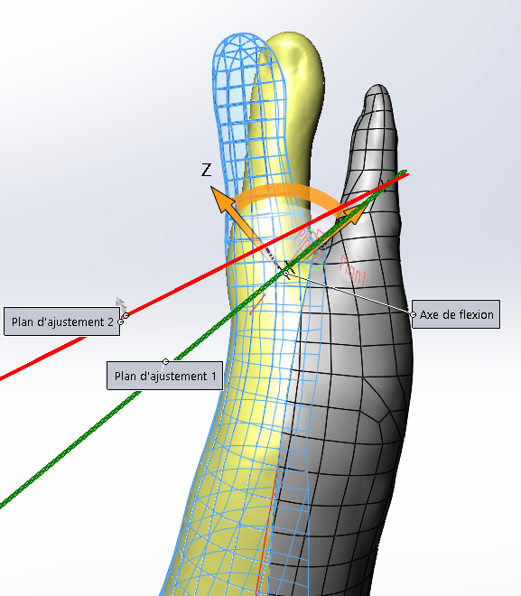
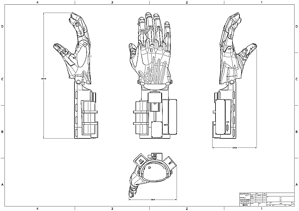
Once the STL is imported into an ONshape’s “part studio”, an enveloping surface is made around the mesh, made of multiple ‘Spline’ curves (generalization of Bezier curves) drawn over successive cut planes. These curves, building a group of sections, each of them wrapping the glove, are then connected (joined) to each other by ‘lofts’. A loft is a surface obtained by interpolation between the different curves, in the form of a NURBS surface (cf wikipedia).


A pile of parallel planes will slice the fist holding the pole. All plans are referenced on remarkable points of the muffle.
On each plane, a closed curve is drawn to surround all boundaries of the displayed STL, thus creating a section. By interconnecting the successive parallel sections by lofts (3D loft function), we obtain the blue envelope (as a surface) which will then be transformed into volume using the “thicken” function.
After having created thickness to the developed surface, having cut the end of the socket to allow the thumb to come out of it, the socket is ready for integration into the new holding system.

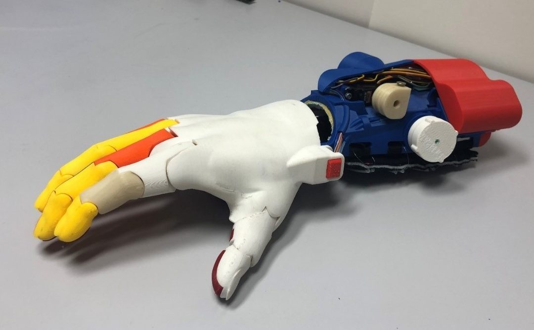
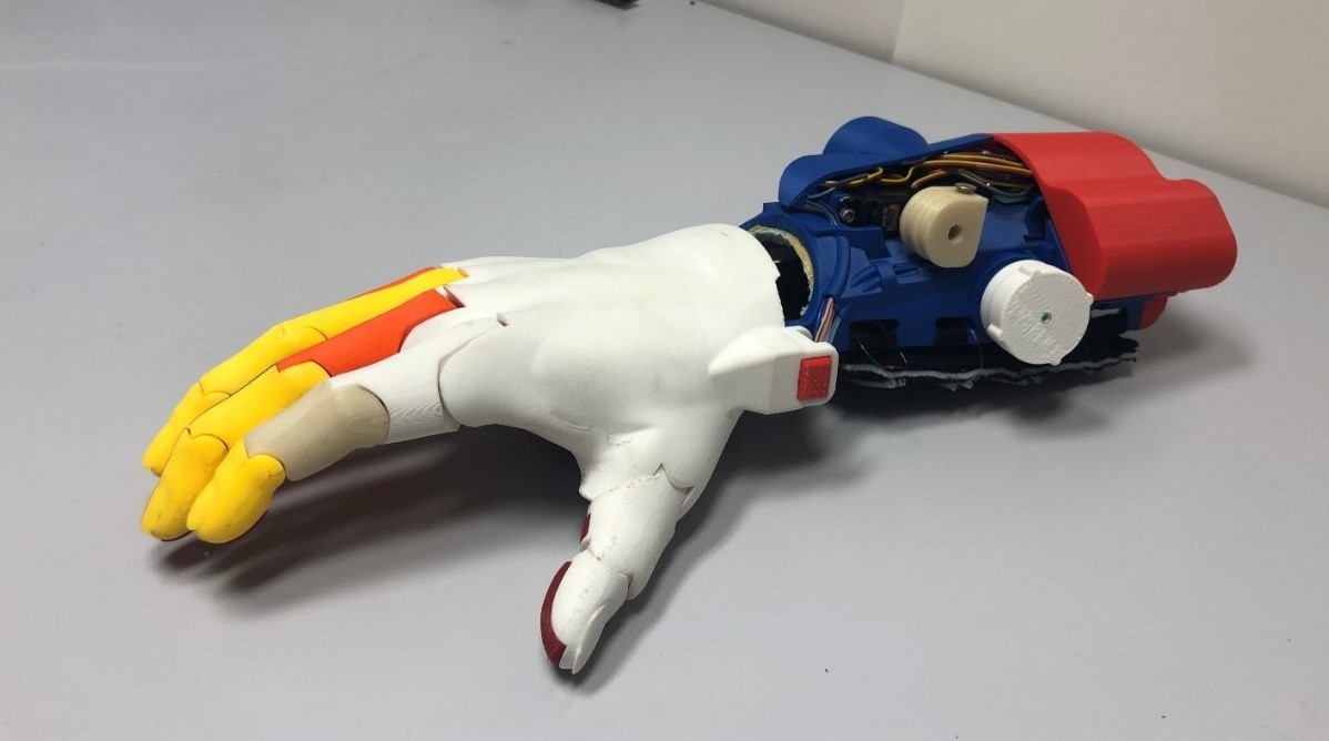
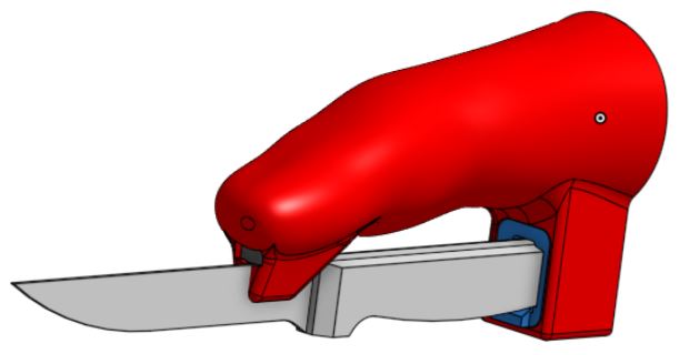
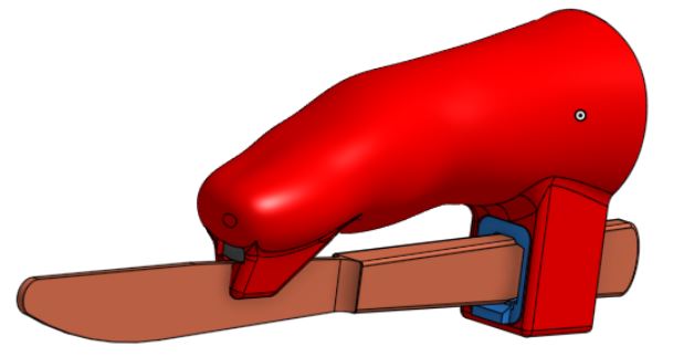
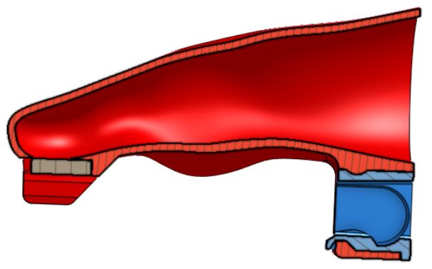
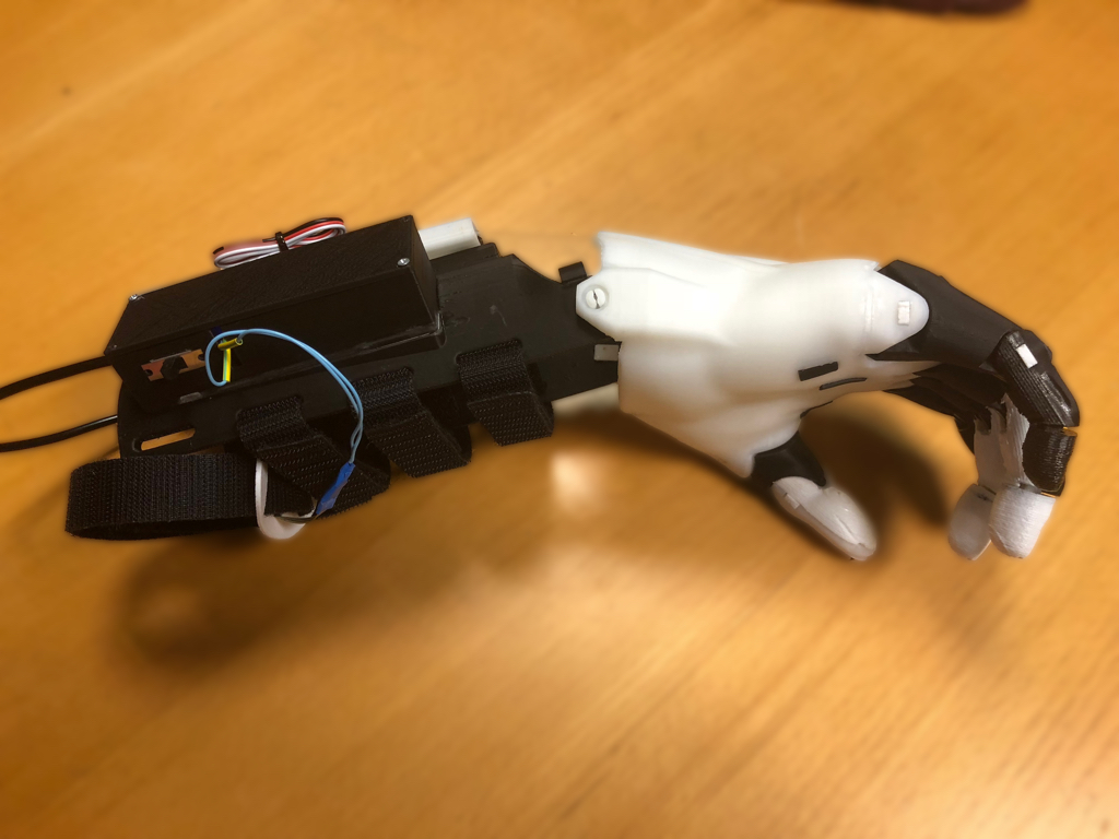
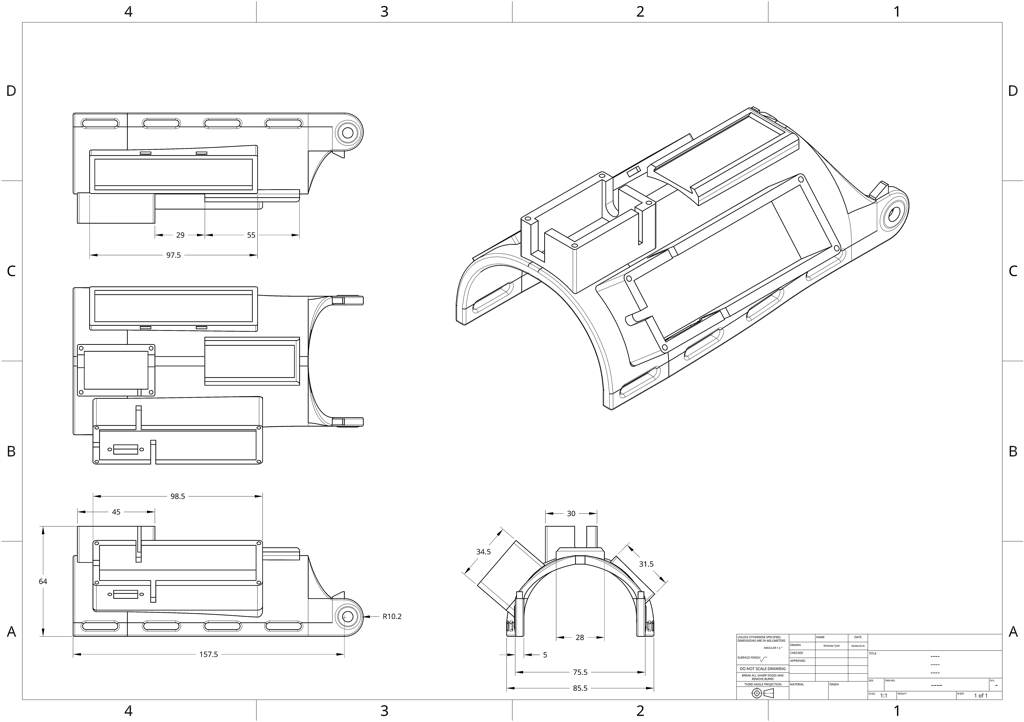
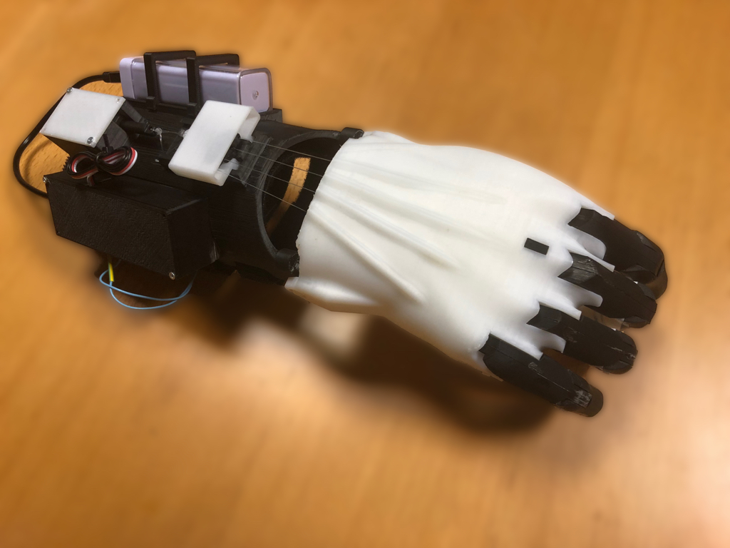
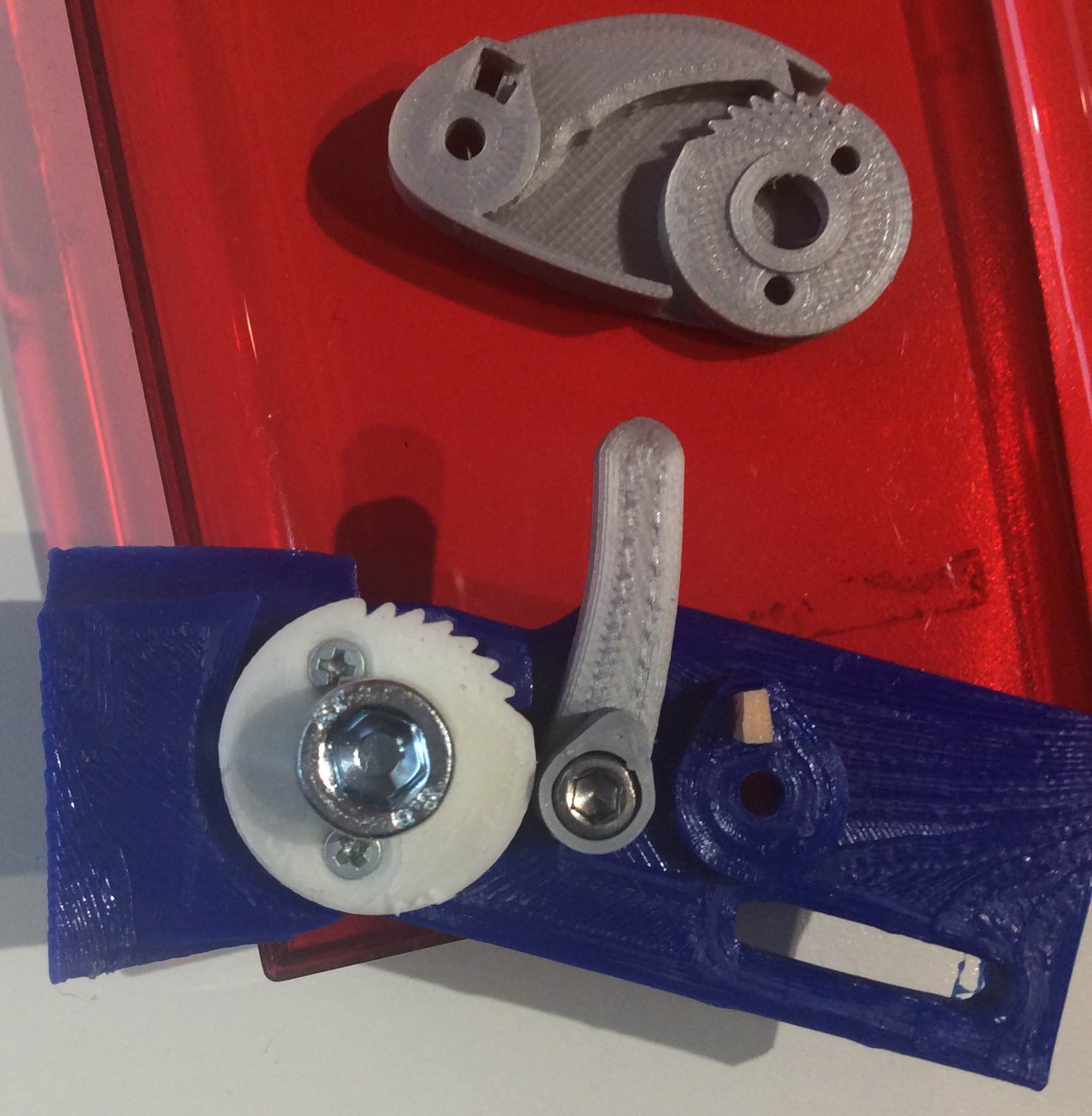
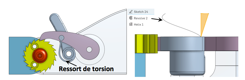
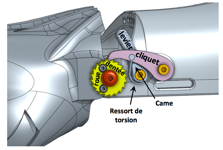
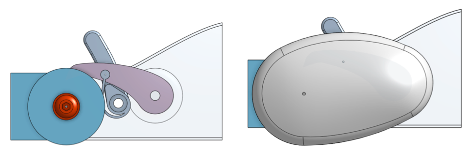
Highlights of the device including a (simple) system.

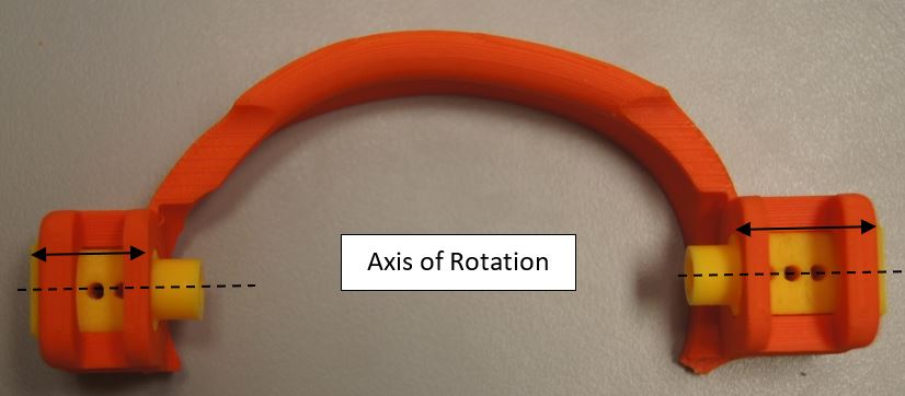
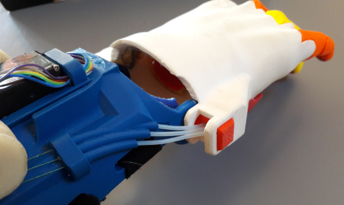
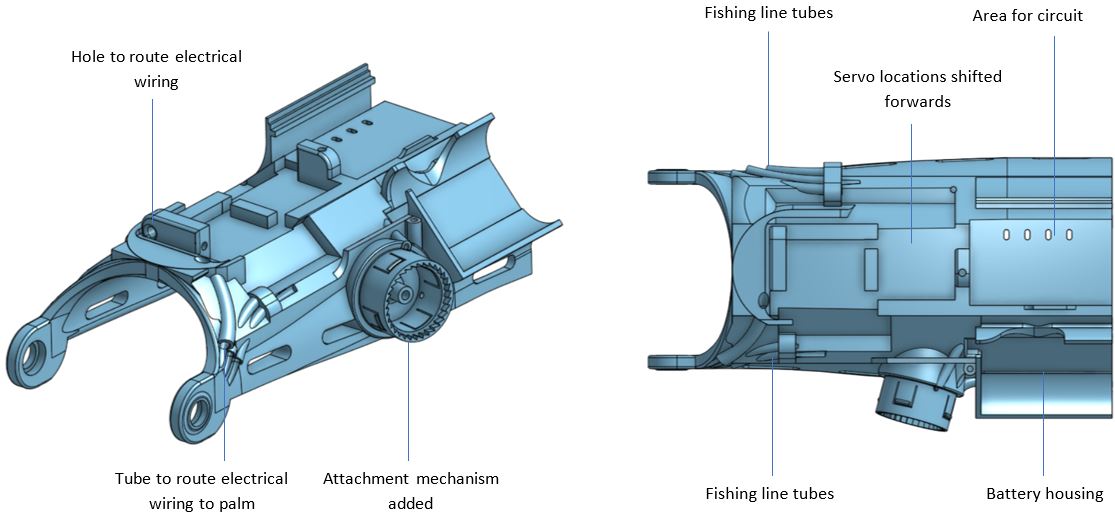
The new device is therefore no longer based on the ball joint principle but on a two-element system :

  • an element on the stick (host)
  • a detachable socket for Manon’s hand.

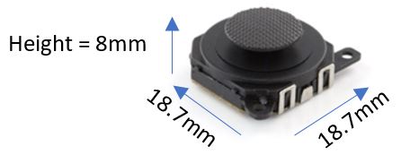
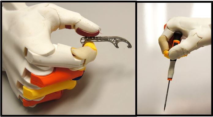
The cohesion of the two elements is achieved by neodymium magnets, powerful enough for the stick to follow each hand’s movements, but detachable enough to allow the release of the socket in case of fall.

The host frame is attached to the stick. The vertical side of the host is on the outside to allow ejection of the interlocking (inwards) in case of any fall. On the inner side of the host, we can see the location where the small circular neodymium magnet aimed at vertical support will be screwed, and the rectangular magnet, more powerful, dedicated to lateral support.
L’emboitement est “collé” sur le bâti grâce aux forces d’attraction des deux aimants.
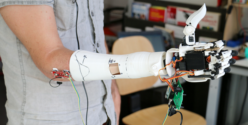
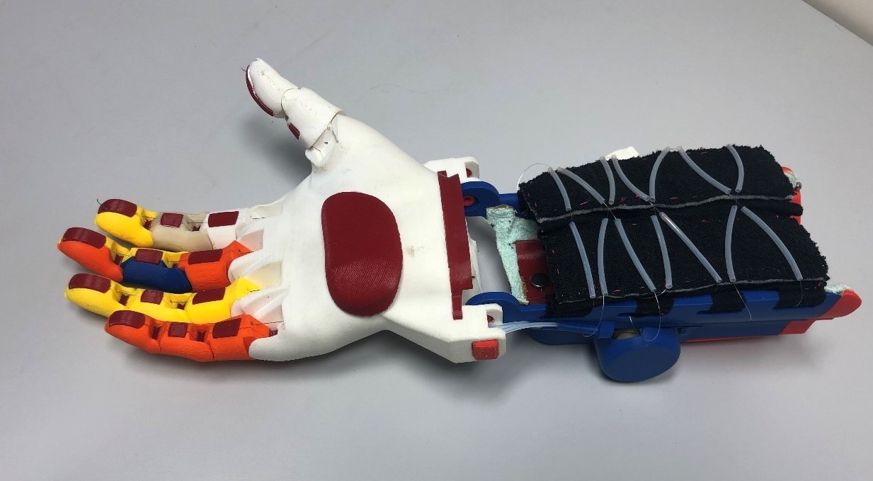
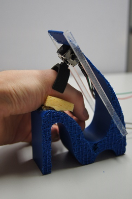
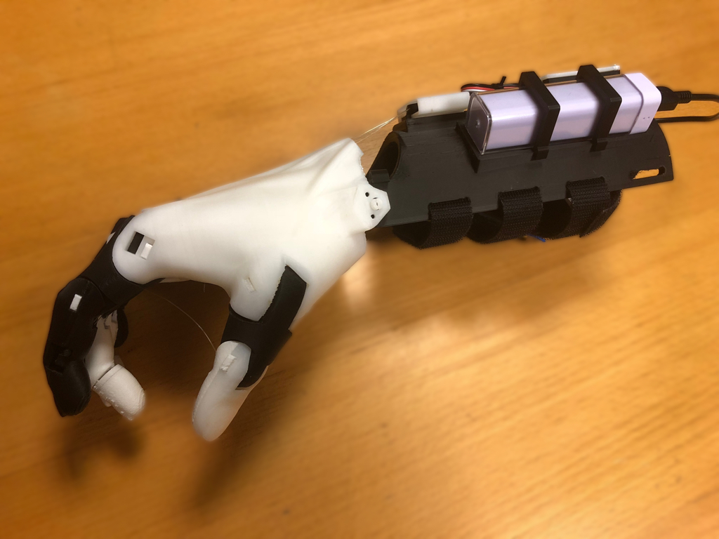
The hand-socket is “glued” to the host-frame thanks to the forces of attraction of the two magnets.
  1. The correct positioning of the interlocking is ensured by a centering dome, and a calibrated location
  2. The holding of the interlocking on the frame is the attractive forces of the main rectangular magnet (40x40x4)
  3. The second magnet (circular) facilitates vertical support and centering of the hand-socket.
-The first prototype validated the functionality of holding the ski pole and its test on a ski slope confirmed our technical choices.

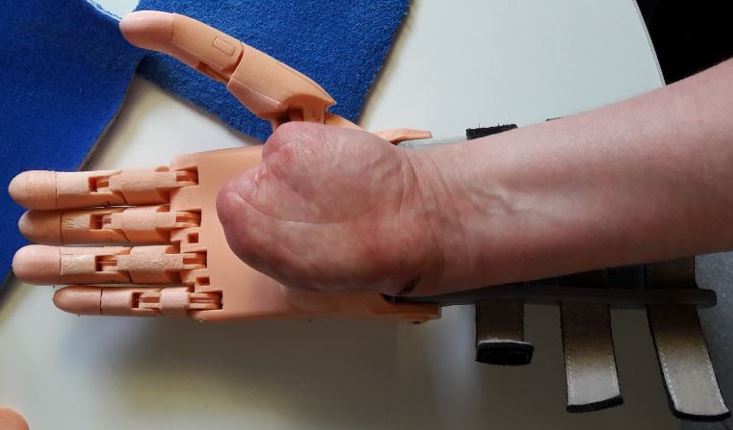
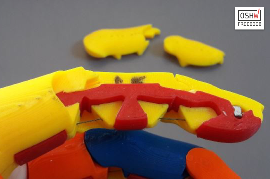
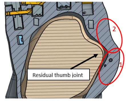
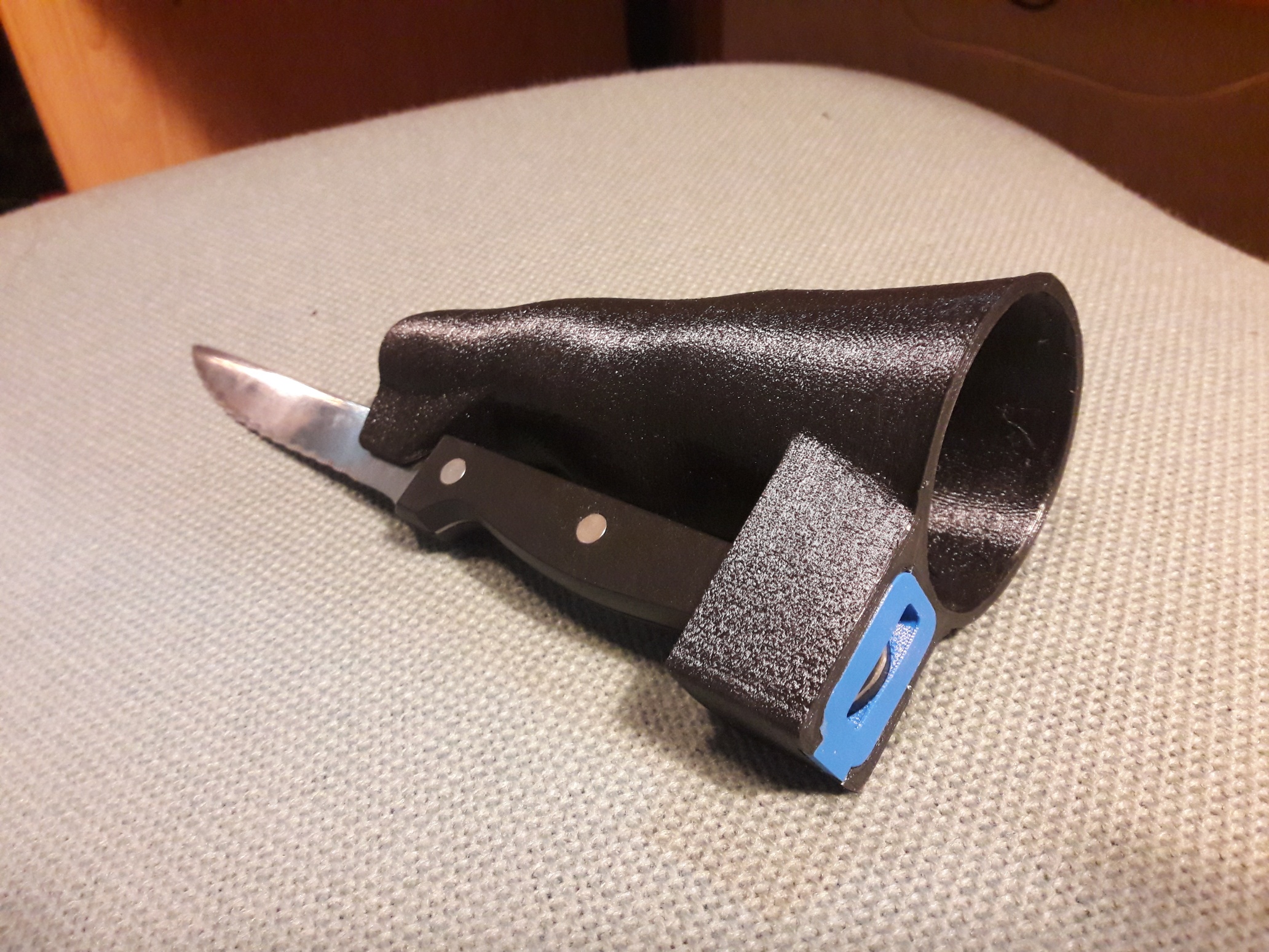
Some small improvements were made to give more room for the thumb and the final version of the interlocking was printed using semi-flexible material (BASF Fusion, with shore mark 65D).

The success of this new concept quickly attracted other parents. So we reviewed (cleaning) the design scripts, so any new requests would be made quickly. The frame (HOST on the drawing) is almost generic, its adaptation to the hand-socket is minimal. On the other hand, the hand-socket being 100% adapted to the size/aspect of the hand and the type of agenesis of the child, its design will be a little more touchy.

Ces adaptations de système à la main d’un autre enfant nécessitent de maitriser l’outil de conception CAO, mais n’est pas aussi compliqué qu’il y paraît. Les fichiers STL du système développé pour Manon ne seraient d’aucune utilité pour un autre enfant. Par contre, nos développements sont open-sources et disponibles sur la plate-forme Onshape, et nous sommes toujours prêts à donner un coup de main 🙂 [© E-nable France]

These system’s adaptations for another child’s hand will require some skill using a CAD design tool, but are not as complicated as it seems. The STL files of the system developed for Manon would be of no use for another child. On the other hand, our designs are open-source and available on the Onshape platform, and we are always ready to give a helpful hand 🙂

Let’s keep in touch.


Electrically Assisted Flexibone Hand

Electrically Assisted Flexibone Hand

About licensing

​ This work (Electrically Assisted Flexibone Hand) is provided under the terms of License Creative Commons Attribution 4.0 International.

This license concerns the whole related documentation, reports, CAD models, testing videos, etc.

The shape of the hand is based on Kwawu hand designed by Jacquin Buchanan.


This project is Open Source Hardware certified :  [OSHW] FR000008

Introduction

This article presents a novel design for a low-cost, 3D printed, electronically assisted prosthesis for a transmetacarpal amputee. The design is the result of a recent collaboration between students from the University of Bath, England (Phil Barden, Thomas Eagland, Jay Pinion, Sevinç Şişman), and a member of Team Gre-Nable, located at Grenoble Institute of Technology, France (Philippe Marin). The team worked to design the prosthesis over a 5-month period, with the final design being the result of extensive force testing and mechanical analysis, rapid prototyping, and user testing. For a more in depth explanation of the final design and the project, please refer to the full report that providing all details. See at the end of this article for even more links and information, CAD model, Arduino code, video records of the tests, etc.

Much of what is presented here are proofs of concept, and it is our hope that by sharing these ideas with the rest of the e-Nable community, others will be inspired to build and improve upon them. Happy reading!

The mission

Most of “robotic hands” developed for amputees are designed with actuator motors integrated inside the palm, like this prototype we have seen on “makea.org”:

“your mission…”, Philippe said to the team, “is to design an electrically assisted prosthetic hand – I mean with motors, battery, mechanics… –  for a lady who lost ‘only’ her fingers. This means there is no room in the palm to put all this stuff”.

Nathalie’s residual hand

Background of the case


The project focused on a lady called Nathalie, a transmetacarpal amputee who approached team Gre-Nable back in 2018 saying she was unhappy with her €48,000 myoelectric prosthesis and asked whether the team could help designing a better alternative for her.

Her primary complaints were that it was far too heavy (weighting approximately 1.5kg, almost three times that of a human hand), and very difficult to control. The prosthesis consequently sat unused in its box.

The design presented below weighs approximately 500g, which is very close to that of a human hand. The approximate cost to recreate it is also close to €200, or less than 0.5% of the cost of her myoelectric prosthesis.


I like it more than my €48,000 prosthesis.

Nathalie

User

The final Prototype features…

  • Force Feedback
    • Pressure sensor in index finger
    • Haptic motors array in gauntlet
  • Attachment Method
    • Snowboard binding mechanism
  • Power supply
    • 7.4V Lithium ion rechargeable battery
    • 2200mAh
    • Providing several hours autonomy

Most of these elements are described in the following sections…

  • Mechanical Design
    • Flexibone finger design
    • Original fishing wire routing
    • ABS & Ninjaflex 3D printed parts
  • Actuation
    • Two servo motors
    • Whipple-tree pulleys
  • Controller
    • 2 axis Joystick
    • Arduino board


Claims


As for a patent description, we claim in this article that, as far as we know, the following elements are innovative in the context of low cost upper limb prosthetics:

  1. Finger kinematics made of a single flexible printed part that allow inter-phalanges bending, together with soft gripping pads in the fingers.
  2. Haptic feedback array in the gauntlet made of a series of vibration motors.
  3. Control by a two-axes joystick taking profit of a residual possible movement of the amputee limb.
  4. Twistable locking mechanism for attachment of the gauntlet on the forearm.

Features detailed Description

Flexibone Fingers


Description:

A novel finger model designed by team Gre-Nable and based on the Kwawu model, using a design with ‘bones’ passing through the centre of each finger and thumb, printed using a flexible 3D polymer called NinjaFlex. The bones are then covered by ABS shells representing the phalanx which give each finger three articulation axes and consistent rigidity. Like usual e-Nable designs (Phoenix hand), fishing wires are used to mimic tendons in all fingers to contract them.

This structure makes the “Flexibone Finger” very easy to manufacture by printing only one simple flexible part, and six rigid half phalanxes (made of ABS or PLA). Moreover, the flexible part realizes two functions:

  • the first one is making three pivot joints,
  • and the second one is integrating pads for a soft contact, that may be coated with rubber like painting (for example Plasti-DIP).

We believe this new Flexibone Finger concept is a major improvement for creating prosthesis, whatever the final type of hand is concerned. For the time being, our Kwawu based hand will benefit from the concept, in near future other type of hand prosthesis may integrate these Flexibone concept. Team Gre-Nable is in the process of developing a simple parametric standard finger based on the Flexibone concept.

The Flexibone Structure

 Testing:

This design was chosen through the means of testing and comparison against other common e-Nable models (namely Kwawu and Phoenix). Two tests were carried out:

  • a force test, to find the design that required the least amount of force to fully contract an index finger,
  • and a grip test, to find which model could grip the greatest range of objects, analysing both object sizes and maximum weight.

The Flexibone hand came second to the Phoenix hand in the force test, both needing considerably less force to fully contract a finger compared to the previous Kwawu design. However, the Flexibone design performed far better than both the Phoenix and Kwawu designs, with it being able to grip objects both larger and smaller, and objects of a much greater weight.

Test rig with servomotor, pulley, fishing line, force sensor, and sample finger in the vice.

Some of the printed series of parts for various parametric studies during the project.

Explanation:

 
The design works by having three areas of the bone which are thinner and are not constrained by the ABS plastic shells. The fishing wire runs up the centre of the flexibone, and when a load is applied to the wire, bending occurs at the three weak points hence contracting the finger. Due to the elastic nature of the flexible polymer, when the load is released from the fishing line the fingers return to their natural resting position.

This bar chart shows a sample result of a force test, comparing the maximum force required to completely bend a variety of fingers, for three different sizes (small, medium size and adult size). It appears that despite its very nice and ergonomic configuration the Kwawu requires more force in the tendon lines. On the other side, the Phoenix hand with dental elastics is still very good with this force criteria.

Fishing wire routing


Description

The routes of the fishing wire (that represent tendon lines) travel from the tip of each finger to the actuation system located on the gauntlet. For most of the wrist actuated prosthetic hands, tendon lines pass over the wrist, and this routing strategy generates a direct link between the wrist flexion angle and the fingers bending position. As we don’t work on a wrist actuated but motor actuated solution, we had to separate the wrist movement from the fingers behaviour. The solution is to route the fishing lines through the wrist rotation axis. This allows the user to bend her wrist freely without altering the tension in the fishing wire.

After having tested fingers behavior, we know that the grip efficiency will be improved if the least force is lost between each actuator and its related finger. That is why we also want to minimise friction along the tendon lines. As expressed previously in this post, we felt that the wire routing strategy may have an impact on tendon line friction and we decided to assess the importance of this impact. This led us to make trajectories as smooth as possible, and to pass wires through PTFE pipes.  

Testing

Because the tested e-Nable prosthetic hands proved to feature a wide range of force to bend the fingers, and this could be due (among other reasons) to differences in tendons routing strategies, we decided to search for a routing that generates as little friction as possible. Several fishing line routes were tested to find the increase in contraction force due to friction, depending on the angle of the curves along the route (see figure below). Additionally, the results were compared to see how PTFE tubing affected this force. The test showed that if the route is lined with PTFE tubes then the friction force is reduced by half, and that the shallower the curves in the route the smaller the additional friction force.

Geometric parameters of tested trajectories for tendon path.

Arch and wrist axis, with tubing holes.

Final tendon path, as smooth as possible, and through PTFE tubings

Explanation

For the fishing line actuation to work while allowing Nathalie to move her wrist, there should be no change in tension of the fishing line, therefore no change in its path length. To achieve this the five routes for the fishing line had to go through the axis of rotation of the wrist as the path length remains constant at this point. The smooth trajectories and PTFE tubing then ensure that the fingers still require a low force to contract as it has a lower coefficient of friction than 3D printed ABS.

Actuation


Description

Two servo motors, each driving a pulley, contract fishing lines that act as tendons in the fingers. The first servo motor drives both the thumb and index finger, and the second drives the remaining three fingers. A whippletree mechanism is built into the pulleys to allow for adaptive grip, as well as tensioner boxes similar to those found in other e-Nable hands.

Pulley CAD model

In case of unbalanced load fishing wire slips on Whippletree.

Explanation

The pulleys are made up of two separate parts, the first being the pulley itself (blue) and the second being the pulley insert (red). Inside the pulley insert a Whippletree is located. The Whippletree allows two of the fingers to be attached to the same piece of fishing line. When one of these fingers is experiencing a greater load acting against it than the other, the imbalance in force causes the fishing wire to slip round the Whippletree, therefore ensuring that other finger can continue to contract without the motor overloading. The pulley insert can also be moved further into the pulley via a tensioner system. As a screw is rotated it pulls the insert into the pulley, therefore increasing the initial tension in the fishing line and tuning the initial position of the fingers.

Controller


Description

 The user controls the prosthesis with their residual thumb joint using a joystick inside the palm.

Sensor types evaluation

After a bibliographic review of sensors classically used for prostheses control and their potential performance, an experimental study of a variety of interfaces have been performed in order to evaluate their usability in the context of this prosthetic hand. The tested sensors were low cost myoelectric sensors, pressure sensors (FSR), and flexion sensors.

Examples of sensors tests: (a) Two flex sensors. (b) One flex sensor. (c) One myoelectric sensor. (d) One flex and one myoelectric sensor. 

All sensors presented an element of inaccuracy, with the myoelectric sensor being particularly unreliable. This was primarily due to difficulty in finding optimal electrode placement.

After analysing the ergonomic capabilities of the recipient, the team finally converged on the opportunity of making use of the mobility of her residual thumb mobility.

A series of small joysticks have been tested, trying to find one easy enough to manipulate with low movement amplitude, and being also as compact as possible to be integrated in the palm thickness. 

First joystick attachment test rig.

Compact PSP joystick

Potential areas to place the joystick

Joystick connected on the palm interface, with sponge foam for elasticity.

Palm-joystick interface part, by offset of the scanned palm.

Joystick and interface integrated in the palm.

Finally, a very compact PSP joystick was found, saving space and avoiding too important modifications of the external prosthesis shape. Also sponge has been put in between the attachment and the prosthesis, to avoid unwanted movements and to ensure the joystick returns naturally to its neutral position.

Explanation


Typically, electronically assisted prostheses use myoelectric sensors as a means of control, and this is a proven method that has seen much success in modern prostheses as a controller. Despite this, the users of such prosthetics often report them to be difficult to control and unpredictable. The myoelectric sensors often provide noisy signals that can worsen if sweat gets between the sensor and the users skin. A prosthetist is also usually required to find the optimal sensor locations which can be costly and time consuming. For a controller, predictability and reliability is key.

In the case of this project, the user is a trans-metacarpal amputee who, on her right hand, is missing all her fingers but retained some of her thumb joint. This joint has a large range of motion and is capable of precise movements, making it ideal for a means of control. To interface as closely as possible with the user’s central nervous system and to therefore implement an accurate controller, the team decided that utilising this joint would be preferable over myoelectric means or other types of sensors.

The joystick controller was successfully used throughout testing with Nathalie using a basic open-close or ‘bang-bang’ configuration. Moving the joystick towards the palm (abduction) closed the fingers, and away from the palm (adduction) opened them. It was proposed that variable speed could also be implemented, as well as being able to turn the system on and off and toggle between grip patterns, although sadly there was not time for this to be implemented or tested properly. A joystick is a very versatile tool that can be used as a complex controller and has been used as one for decades in devices like video game controllers. It’s therefore highly likely that, with training, a user could learn to give more complex commands to the prosthesis.

Force Feedback


Description

A pressure sensor in the index fingertip indicates to the user the grip force being applied to an object by vibrating one of four haptic motors in the gauntlet. The pressure sensor is entirely concealed within the NinjaFlex fingerbone. The haptic motors vibrate on the surface of the user’s forearm, with a different motor vibrating depending on the force applied through the fingertip. The motor closest to the hand vibrates upon contact with an object, and the vibration moves further up the forearm as the force increases.

Left: Index finger and sensor location. Middle: partially disassembled index finger showing the conductive fabric route leading to the pressure sensor in the fingertip. Right: Haptic array in the gauntlet made up of four vibration motors.

Explanation

Researchers have found that implementation of force feedback is of great use to an individual in terms of improving embodiment of a prosthesis and improving performance when grasping, particularly for delicate objects. The implementation of force feedback was therefore explored in this project using low cost materials. Conductive fabric was used in lieu of wire to avoid the wire fatigue that would inevitably occur in the finger under repeated flexion and extension. Although not done so here, pressure sensor(s) could also interface with the actuators using the Arduino as a means of closed-loop feedback (i.e. limiting the maximum force that can be applied to an object).

Attachment on the forearm

Description

In place of a usual Velcro straps or similar, a more comfortable option has been investigated by the use of soft fabric that is tightened by a fishing wire and a locking mechanism inspired by BOA Fit system (often used for snowboard boots) and its use by Younes Zitouni in the e-nable.fr community.


Parts of the twistable locking mechanism

Comfortable gauntlet tightening mechanism

Test

In order to assess the maintaining potential of the solution, the wire strength was tested up to breaking force. Also different routings were tried, and it was seen that a double helix (cross hatched method) routing was a better option to have a uniform tightening and distribution of the load, together with the easiest releasing process.  Several types of fabric were compared to converge to “Tissus3D” which provides a comfortable feeling to the user, and, in addition, is often used by prosthesists for skin interface.

Explanation

Based on the binding of a snowboard boot, this fastens the prosthesis to the user in a similar way to a shoe lace. This method was developed due to the user being unsatisfied with the Velcro straps on her existing prosthesis.

Optimizing finger configuration


Description

It appeared during tests with Nathalie that she was often not able to grasp a bottle with our prototype. This was due to fingers contracting so that the distal joint rotated fully before the intermediate and proximal joints began to bend. This led to the distal bone making perpendicular contact as seen in figure Figure 16‑11, followed by the object being pushed away from the palm. To allow the prosthetic to grip the objects, a more natural order of contraction needed to be achieved.

Test

Below is compared on the first line of images the bending process of the original Flexibone finger, and on the second line the bending process of the final one.

Explanation

After a series of tests, this issue was solved by increasing the thickness of interim and distal flexible joints in the bone, by 25% and 50% respectively (see figure below). A drawback is that it increases the force needed to completely bend the finger (see curve below). Due to time constraints, a final global decrease of thicknesses in all three joints has not been investigated.

Grip patterns


Description

Thanks to the Arduino code and the two-axis joystick, several functionalities have been implemented. And others could be developed if needed. The main grip patterns are described on the following figures: finger point grip, power grip, two-point tip pinch, lateral grip.


Final Gauntlet

Here is a summary of the final gauntlet layout and casing.


Potential improvements

Among many ideas to improve technical or functional aspects of the Flexibone assisted hand, here are the main priorities:

  • Thumb rotation plane: The orientation we made for the thumb does not really allow opposition with the forefinger (see power grip image above), which makes it difficult to grap some objects. Maybe we did not put the same way as the original Kwawu… This plane could be slightly modified, and the thumb movement amplitude also increased.
  • Haptic feedback : The position of the pressure sensor in the forefinger tip does not act always the same way depending on the contact configuration with the object. Could we find a better configuration, or a different sensor, so that the contact force would be properly detected in most situations? Also which haptic motors is activated seems difficult to figure out by the user. She says she feels vibration in the gauntlet but she feels difficult to know on which location.Reducing the contraction force of the fingers
  • Reducing the contraction force of the fingers. To improve finger contraction strategy we increased some of the Flexibone joints thicknesses, which finally increased the bending force that the fishing line has to provide. The drawback is that the greater the force that is lost through the tendons, friction, and bending of the fingers, the lower the force that remains for gripping objects. We should now investigate the possibility to decrease the flexion force by decreasing all joint thicknesses, keeping the relative flexion order and of course keeping a reasonable mechanical strength of the fingers.

A full open source project


Not only this article, but all data generated along this project is released as the open source “Flexibone Assisted Hand” under a licence Creative Commons Attribution (CC By).   We are happy to provide the community worldwide with:

  • Finally, if you just want to print the parts and build a copy of this, you can find STL files on Thingiverse
  • We will appreciate if you follow any works on the project with comments.

Acknowledgement

Thanks to the team Gre-Nable Philippe, Patrick, Fabien, Marie-Laure, for allowing us to work on this amazing project.

Thanks to Frédéric for his coaching in project management.

Thanks to all the Team of GINOVA, the University Fablab in Grenoble Institute of Technology for his technical support during this project.

Thanks to Patrick also for his help in publishing this article on the Team Gre-Nable blog.

And of course, many thanks to Nathalie (and her family) for her confidence in our work, and for being available for several tests along the project.

During the final meeting, from left to right: Tom, Phil, Nathalie, Sevinç, Jay. 

A knife holder for a child

A knife holder for a child

The context 

Lina is a 5 years old girl when we meet her for the first time. She was born with a malformed right hand equipped with two fingers. One of these is weak. She cannot flex both of her fingers, but only move them laterally as a kind of needle nose pliers. And she is very comfortable for most of everyday life activities… except for some actions that she cannot perform. And an example is holding a knife. Her parents are used to help her cutting meet, and she is used to push rice to the fork (which is handled by her left hand) with her two fingers.  

But now she has to have lunch at school, or sometimes diner in  a restaurant, and she probably feels not so comfortable in front of other children.  Thus Eric her father asks e-Nable community if someone can help in developing a kind holder for Lina.

Modeling of a fitting socket

After a first meeting with Lina and Eric, we consider that a standard e-Nable hand cannot fit the need of Lina, and we decide to develop a very dedicated knife holder.  It will be made of a socket in which Lina can insert her right hand, and some specific shapes where she can fix different kinds of knives.

Hand casting 

The first operation is to get a model of Lina’s hand. This is done by casting her hand in pink Alginate to get a positive plaster copy.  

Shape modification

Unfortunately she bent her wrist during casting operation. After the 3D scanning and reverse engineering process that leads to a clean digital model, the next operation to get a proper model usable to make a comfortable socket is then to unbend the CAD model. This is performed thanks to a specific “flexion” function available in SolidWorks. This allows to put the hand inline with the forearm, and also to put the two fingers closer to each other.

Design of the socket

The next step is to design the socket. We come back in our collaborative CAD software, Onshape, to draw a few sections and build a “loft” that approximately fits Lina’s hand. Then two offset operations of surfaces lead to the inner and outer shapes of the socket, with 3mm gap dedicated to put a comfortable 3D fabric that can absorb moisture and can be easily removed for washing. 

Designing the knife holder

The input information for designing a knife holder it to have an idea of the types of knives that will be used with this device. Eric, Lina’ farther, provided two CAD models (he drawn by himself) of knives available at home: the “knife to push” and the “knife to cut”.


Then we started with the idea of fixing the knife handle in a flexible interchangeable part that should fit both types of knives, and to add a simple slot to center the blade. In the first prototype the blade has been tied with adaptive strap made of Velcro type band (ID-Scratch).

After validation of the orientation and position of the knife by Lina, for the second version the strap was replaced by a simple neodymium magnet. You will find below a photo of the first version in test (pushing knife), and several CAD views of the last version.

And then…

Lina is happy, she can eat without asking for help to her classmates;

Eric is happy, Lina eats now without pushing noodles with fingers.

Eric asked for advice because (and that’s also good news!)

  • he is in the process to learn how to design with Onshape. He already made a new insert (the blue part on screen shots above) that will fit another knife handle.
  • And he is in the process of buying a 3D printer and we hope him to become a new maker within e-Nable France community 🙂


The CAD models are available for inspiration, adaptation to other cases, and hopefully for improvements under cad.onshape.com, if you have an account (free for non profit activities and public models), you just have to search for “Team Gre-Nable : knife_holder” among the public models. 

Please just let us know if you design an adaptation of this!


Design Of An Assistive Upper Limb

Design Of An Assistive Upper Limb

Here is the final report written by 3 graduate students who worked during 4 months full time to build a proof of concept for an assistive system dedicated to ease utilization of e-nable printed apparatus. They together investigated the state of the art in low cost assistive upper limb prosthetics, and proposed and tested a set of technical solutions.
Thanks to Júlia FIGUEREDO DE ALENCAR, Khumbo NYIRENDA and Nicholas TYRIE, who came from the University of Bath (UK) to perform this semester in the school of Industrial Engineering in Grenoble, for their high involvement in this project and for the quality of this report.

Philippe

Thesis advisor, Industrial Engineering School, Grenoble Institute of Technology

You can read or download the report of the 3 students : Responsible_Design_Final_Report. Happy readings.

Wrist Lock System: Relieving wrist bending

Wrist Lock System: Relieving wrist bending

Context:

Classically, bending the wrist enables handling objects with an E-nable hand prosthesis (Raptor or Phoenix). But, we identified that this bending movement, necessary to trigger a grip, led to tire the user of the prosthesis with time.

After Nathalie has experimented her hand prosthesis (see post), it became obvious we had to find a solution to relieve her wrist muscles. Nathalie is an adulte who suffers from an amputation of her right hand (after her wrist) after a healthcare-associated infection. Once she contacted E-nable, she was equipped with a first customised prosthesis. However, as she used it regularly – to handle tableware, purse, or to bike – the fatigue of its muscles becomes too important.

Need and process :

It becomes necessary to enable a grip position of the prosthesis without effort from the user of the prosthesis. Additionnaly, this feature has to be as less bulky as possible and easy to use.

Different solutions were considered to maintain the tension in the finger wires in order to lock the grip position. However, no trade-off was found out. As an alternative, we looked for a system locking the hand in the grip position with no effort. Thus, below proof of concept has been used as a guideline, based on a ratchet working principle.

Row idea, based on ratchet working principle, for locking the grip position of a hand prosthesis with no effort from the user.

To approve such a concept, a first prototype has been designed and printed. Palm and gauntlet proxies have been replaced by simplified parts, printed in blue on below pictures.


Proof of concept, every parts were printed in PLA

All the design was realized on « OnShape » for all the advantages listed here.

Design : first version

Once the proof of concept approved, a first functional version has been realised:

First version of the « Wrist lock». On the left, in open position. On the right, in close position.


Design

On the kinematic side: the lever cam, as in final version lifts the tooth (cliquet in french) to the open position, when the lever is pulled to the right hand side. The cam is then locked by a small hole in the tooth.  Le flex spring, printed in Ninjaflex, is compressed, to lock the open position. When the user pulled the lever on the left hand side, the flex spring lowers the tooth. This same flex spring maintains the contact between the tooth and the ratchet (roue dentée in french) by compression/extension alternatively.

On the material side, we started by printing tooth and ratchet in PLA and iGlidur (IGUS). But strain wear due to the ratchet/tooth contact were too important. So finally, we machined them in metal (aluminum/steel) to limit wear effect and to support efforts generated by an adult (for instance, the screws used to attach the ratchet to the palm quickly get loose because of these efforts. They have been replaced by two nuts-screws). Ratchet was bought at a specialist and tooth was machined in our hackerspace with a CNC DIY. Notice that the « wrist lock system », in its final version could be nevertherless fully 3D printed if the final user is a child since the generated effort would be lower.

First observations after print and assembly

After assembly, the system works well. However, we observed quickly a permanent deformation of the flex spring, mainly in open position. Likewise, the cam, in PLA wears against the metallic tooth

So we have redesigned these two elements to make the system robust. Purpose was to avoid the wear of the cam while not loosing the elasticity of the spring.

Second version

For the second version, a torsion spring has been introduced to solve both previous drawbacks: 

Second version of the « Wrist lock system ». On the left hand side, the cam and the flex spring have been replaced by a torsion spring. This spring link the lever to the tooth. It lowers the lever and maintains the contact between the ratchet and the tooth in close position. Likewise, when the lever is in open position, the spring raises the tooth. On the right hand side, the spring has been designed with the helix function of Onshape.

Design

We have first considered the wear issue. This wear comes from the friction between the cam and the small hole in the tooth. This contact is necessary to switch between open and close position. So both features have been deleted, replaced by the torsion spring. It is now a part of the lever and slots into the tooth. Thus, both part are solidly linked. So, tooth can switch between open and close position when the lever is pulled toward the right or toward the left respectively, through spring action.

Then, when the lever is pulled toward the left. Tooth switch in close position. Then, when the wrist bends, torsion spring maintains the contact between the ratchet and the tooth by means of its elasticity. Thus, the lower part of the tooth, from version #1, becomes useless and is deleted. 

In this new configuration, the torsion spring does not require to bear high efforts. Indeed, beeing attached under the tooth, it is only used to i-maintain the tooth in open position when the lever is on the right, and ii-maintain the contact between the tooth and the ratchet in close position. Such low efforts limit the risks of wear and failure of the system.

Observations after print and assembly

After assembly, the system works well. However, the torsion spring is not strong enough to switch the lever to the open position when the tooth is in contact with the ratchet. Likewise, in close position, when the wrist bends, the spring is in contact with the ratchet and so wears.
Some final adjustments are then necessary.

Final version and finishing touch

In its final version, lever and tooth have been pulled away from the ratchet (a few milimeters) to avoid generating friction between the ratchet and the torsion spring. The cam lever, from version #1, has been re-introduced to help switching from close to open position. The torsion spring then ensures to remain in open position:

Final verson of the « Wrist lock system ».  The cam lever has been re-introduced but only to help switching from close to open position. The torsion spring then ensures to remain in open position.

After assembly, this version is retained.

Finishing touch

Once the final design retained, two finishing touches have been added:

  • A spacer is mounted on the ratchet to protect Nathalie from the sharp metallic teeth. 
  • A cover is added for aesthetic purpose.

Finishing touch for the final version of the « wrist lock system ». On the left hand side: a protection spacer to avoid any contact with the sharp metallic teeth of the ratchet. On the right hand side, an aesthetic cover.