Matteo’s arm: Technical Aspects
Matteo’s arm has been designed mainly based on the Unlimbited Arm , and more precisely the Alfie Edition.
This page will document why and how we proposed some modifications of the UnLimbited Arm. The main set of modifications intends to improve “grip” efficiency.
We then also propose to modify some other details:
- modification of the forearm shape to make it better aligned with the arm cuff when the elbow is open
- cuff printed flat and bended in several steps (easier to print and stronger result)
- insertion of a fun magnetic functionality in one finger.
Note: The STL files and size information are provided on Thingiverse.
How to get a firm grip with the Phoenix hand mounted on an Unlimbited Arm?
As we said in the “story page“, the main goal was to improve the grip efficiency to allow the user to take a variety of objects. The main ideas are in 3 categories:
- minimize friction so that a maximum effort is actually transmitted to the fingers;
- use an efficient whippletree [John Diamond] to ensure almost all fingers come to contact with the manipulated object;
- put on almost every potential contact surface both a soft material (flexible/deformable) and a high friction coating.
These 3 points are described more in details below.
Reducing friction along the tendons paths
In the Unlimbited arm mounted with Phoenix hand, all tendons go through a complex path from the fingers to the tensioner situated on the cuff. Thus a relatively high friction occurs. For example, if we have a look in the hand, the standard “S-shaped” path (red line on the figure) is needed for the tendon to path around the hand of a standard patient with his(her) palm in the prosthetic hand. But for a person without a wrist, there is enough place in the hand to go straight to the base of fingers (yellow line of the figure). This simple modification can drastically decrease friction within the hand. The first idea is thus to drill the yellow holes and leave the tendons cross the hand straight. The second idea in the same area is to insert PTFE tubing in these holes. This PTFE tube is 2mm outer diameter, and around 1mm inner diameter. It has been sourced from a hobby shop (RC models).

Direct path for tendons in the hand (click to enlarge)
For the thumb, a continuous PTFE tubing drives a kind of Bowden large radius path (yellow dotted line on the picture). This thumb tendon tube has been maintained in place in the hand by PLA deposited with a 3D printing pen (3Doodler for example). Another gluing or welding solution may be used as well.
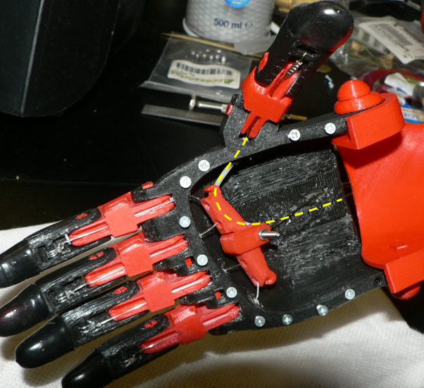
Thumb tendon path with PTFE tube (click to enlarge)
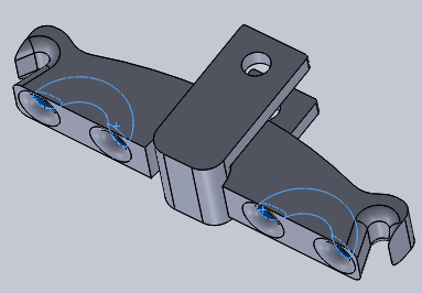
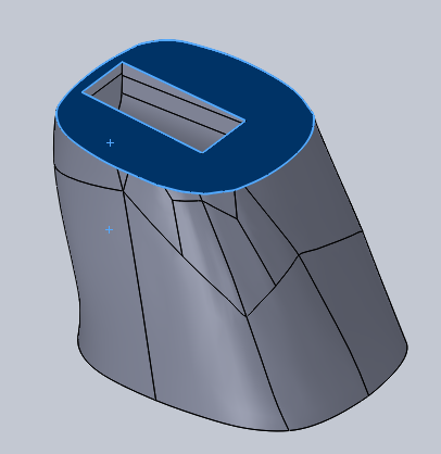
Finally along the forearm, a PTFE tubing can also be inserted for each tendon (and we will see below that we only need two: see the red zone on the CAD image below).
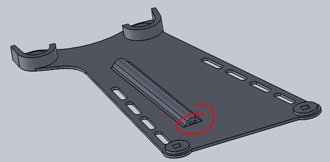
Holes for PTFE tubes in forearm (click to enlarge)
Integrating a whippletree
On the Unlimbited Arm Alphie version, the fingers are associated by pairs (see stringing process). We expect that a full whippletree system as proposed by John Diamond would be more powerful to ensure the best possible contact of all fingers on the manipulated object.
As we have enough room inside the hand, the second idea is then to place the whippletree in the hand, so that the tendons are as short as possible, with minimum friction. It is simply made of a whippletree bar and a fork. Only one tendon then goes from the hand to the cuff. Note that this tendon should be very strong and rigid as it has to withstand the force of 4 fingers simultaneously. A fishing line made of steel core coated by Nylon (outer diameter 0.5mm) is used. This main tendon is fixed to the fork by a M2 or M2.5 screw (still too long in the picture) and a bowline-knot.
Whippletree integrated in palm cave (click to enlarge)
Note the small hooks at both ends of the whippletree bar: the may receive two elastics that will connect to the central screw, to make a balance in order to ensure that the movements of the two pairs of fingers initiate simultaneously despite a possible difference of friction in pins joints or difference of stiffness of the dental elastiques. They were not required on Matteo’s hand.
Whippletree – 3D design
The video below demonstrates how our whippletree is functionning.
Combining flexible material and adhesion coating
Case of fingertips
The last phalanx of each finger should be as sticky as possible on the manipulated object. Makers from e-Nable community often use Micro Gel Fingertip Grips, but when we ordered the smallest size available (size 3), it appeared that they were too big for the small hand we made for Matteo. They just fitted its thumb size, not other fingers. Moreover, we didn’t want to add thickness over the fingers, as we expected to keep the fine design of the Phoenix hand and fingers. So we decided to develop a different solution to improve the grip.
Tip-top assembly
After numerous trials, we converged to a combination of rigid PLA with flexible PLA, and a layer of sticky material. We thus separated the distal phalanx in two parts. The first half is made of rigid PLA in order to withstand the movement force (the tendon is attached to this part), and the tip of the finger is made of flexible filament (after trials with a variety of flexible filaments, we used Ninjaflex for the final version). The printing parameters need to be carefully tuned[1] so that the fingertip is rigid enough to support the catching force, but has a deformable surface to maximize the contact area with the manipulated object. The assembly of rigid and soft materials have been initially made by the use of a double extruder printer. But we preferred to publish a version that can be made with a single extruder. So the two parts of the distal phalange are printed separately and assembled by taking advantage of the flexible part. It results in a strong assembly but removable tip if needed. No glue needed here. The new parts have been called “tip” and “top” in the STL files list.
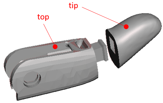
Each distal is split to create a “tip” and a “top”
(click to enlarge)
The next step will be to take advantage of the removable tip part to hide the tendon knot inside this assembly. This is freeing more surface to put adhesion coating on the inner side of the distal phalanges.
Finally in order to improve friction coefficient, these soft fingertips have been immersed in PlastiDip to be covered with a kind of rubber shell.
Case of the palm
The same idea of placing a soft and sticky material is also applied to the palm. We started from the hand generated by the .scad file of the Unlimbited arm, removed the rigid palm, and made a new one that will be fixed by a number of 2.2mm x 6mm screws. We set up the thickness and added a few bosses distributed quite like in a human hand and that will be printed with flexible PLA.

Palm cover made of PLA and Flex
This palm is printed with three 100% infill layers of PLA (that is 0.6mm) to provide a certain rigidity, then the filament is replaced by NinjaFlex to continue printing the flexible layers and flexible bosses. After printing the palm is covered with a thick layer of PlastiDip.
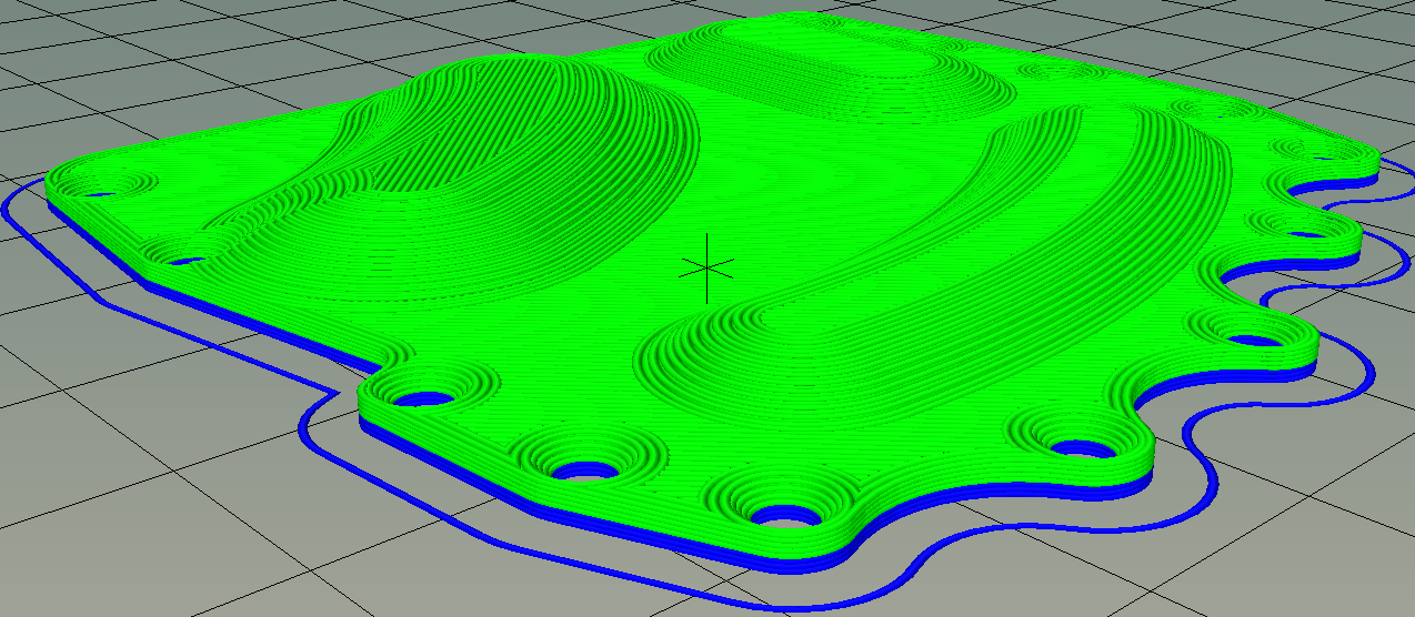
Blue =PLA, green = Flex
On the proximal phalanx
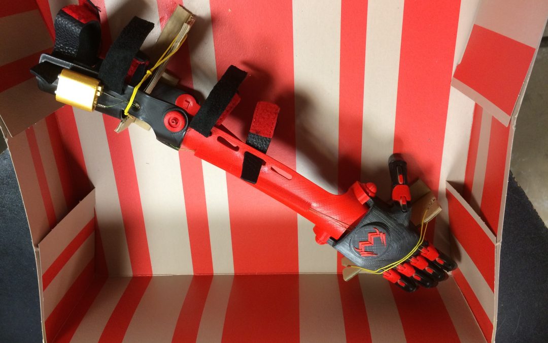
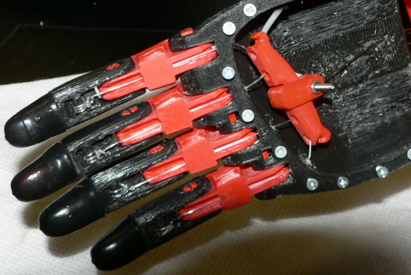
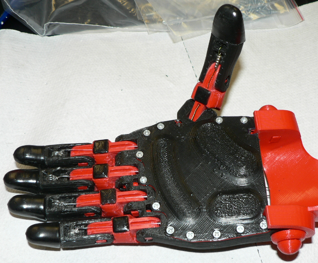
Finally small square pads made of Ninjaflex and coated with plastiDip are glued under each proximal phalanges. The following figure shows the look of the final hand.
Put fun and useful add-in: a super power for Matteo
As most of children we were sure that Matteo would like to be a super hero, with super power. We also wanted to provide him with a additional possibility to catch small iron objects with his new hand. This has been done by including a small neodymium magnet into the “tip” part of the forefinger. A void has been reserved in this part, and a pause in printing process allowed to insert the magnet. The magnet size for the forefinger was diameter 3mm and length 6mm. We also made some tests with a diameter 6mm length 4mm included in the thumb tip. Both version work well, the thumb being more powerful (thanks to the bigger magnet), but the forefinger seems to be easier to use.

Split view of the forefinger tip.
Pause during print for inserting neodyme magnet
Both STL files are provided in “Thingiverse Matteo release“. Magnets have been provided from this shop (www.sanf.fr).
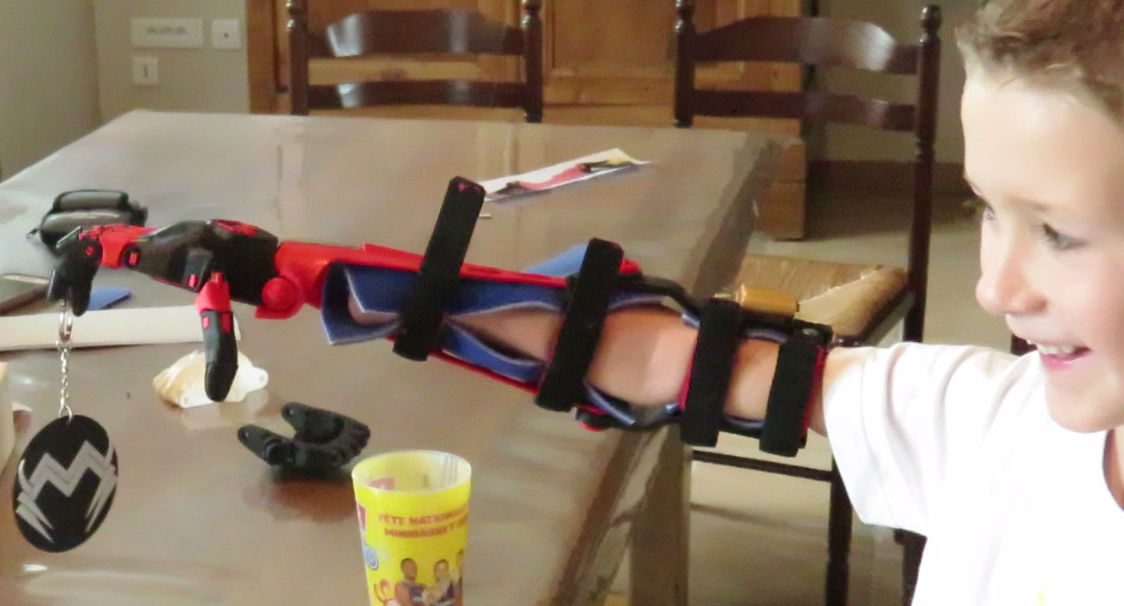
Matteo picking a badge with the forerunner
Forearm modifications
The main modification we did on the forearm model is linked to a misalignment between forearm and arm cuff.
The problem we faced with
After printing and bending first forearm and cuff, and trying to make the assembly, we discovered that we had to make the forearm quite flat to be able to insert pins.
Original forearm
Pins axes distance

Cuff forearm misalignment
cuff arm aligned
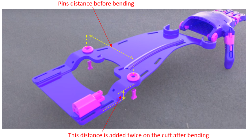
Analysis
This seems to be due because the distance between pins axes is designed to be equal on cuff and forearm before the bending operation, as we can see on the same video (second screen copy). And because of the S-shape of cuff arms, the width of cuff will become bigger than the width of forearm after bending, which makes it difficult to assembly, and also generates a misalignment (see third screen copy aside) of the arm and forearm on the final prosthesis which may hurt the arm in case of intensive use.
Solution proposed
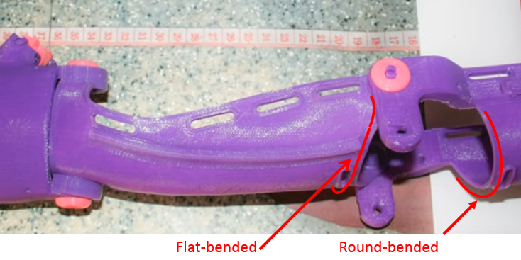
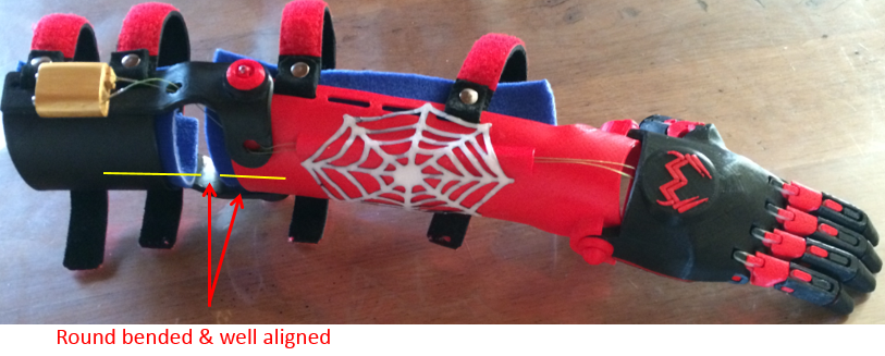
That is the reason why we decided to modify the forearm pins distance, so that the final distance after bending of the forearm is the same as on the cuff. As a result, the forearm becomes well round-bended, and moreover the misalignment is suppressed.
Result
The final arm of Matteo is shown on the fourth picture beside. One can see that the forearm is well round bended, and well aligned with the cuff shape. The STL file provided includes this width modification.
Cuff modification
As the idea of printing parts flat before thermal bending with hot water or hair dryer seems to be a very good process providing both easy printing and really increased strength (no more delamination of PLA layers under load), we wondered why it has not been done for the whole arm cuff, and decided to try it.
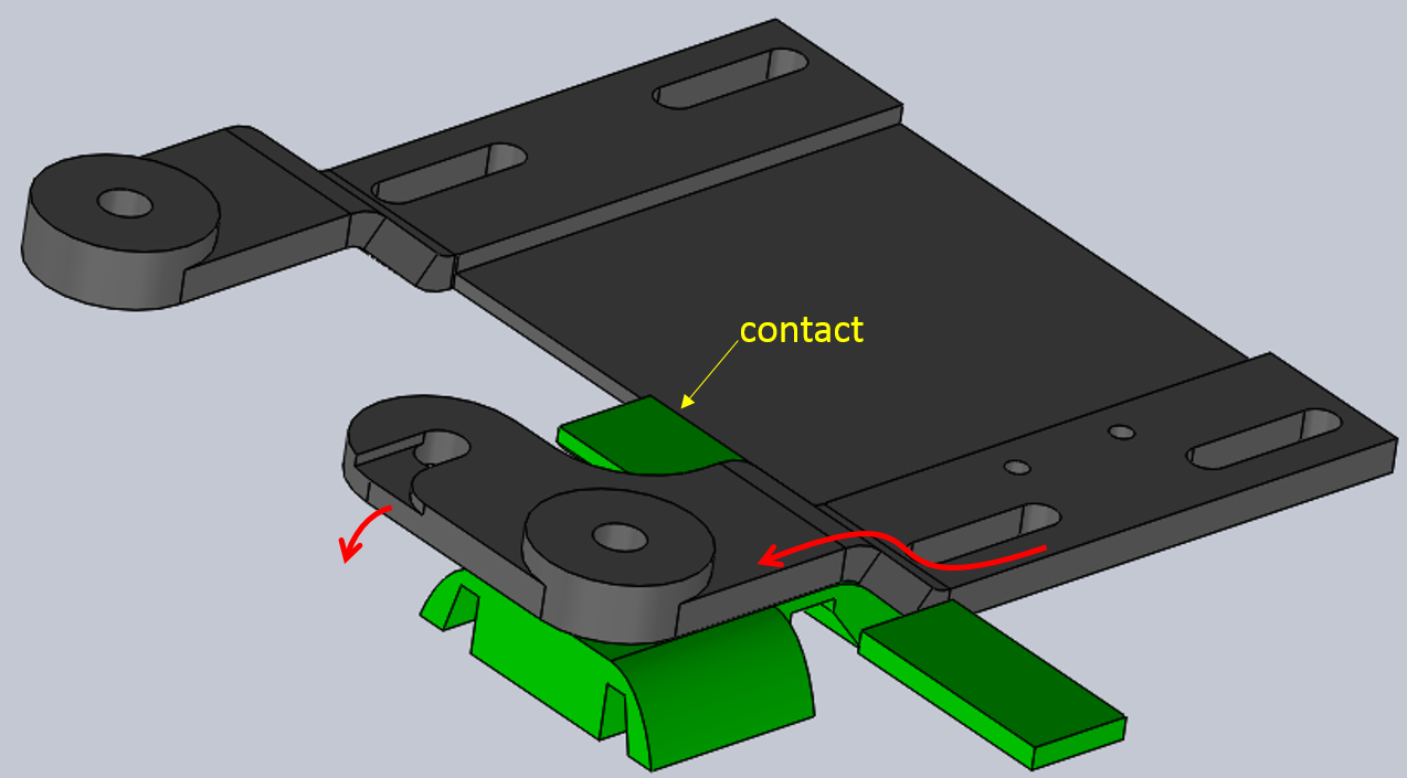
Thus starting from the good shape of the “UnLimbited” cuff, we redesigned it with regular thickness to make the two arms bendable, and flattened to make it printable. Then a new jig has been designed to ensure the original dimensions after bending. The green part on the second picture is the new jig. Red arrows show the process of bending the S-shape of the two arms of the cuff.

Flat printable cuff
Bending cuff arm
Note also that we propose to slightly bend the lever on the cuff, which pulls the tendons (see on third figure aside, yellow area). This is just to avoid having this lever prominent from the arm. The drawback of this modification is that it slightly decreases the distance between rotation axis and pulling point, thus it requires a bit more angle of the arm for the same movement of fingers.

Lever and tendons
And finally, a little problem we discovered too late to make the modification on Matteo’s arm, is the thumb tendon is too long when the hand is completely open (see third figure, green area), and we fear that it may catch something (door handle, etc.) when Matteo is playing or running in the house… A solution could be to also put a short PTFE tubing or anything else to close this area, as there is no movement of the cables here except during the tuning phase.
Notes : Slicing parameters: with a nozzle of 0.4mm and a layer thickness of 0.1mm; 2 perimeters, 3 top/bottom solid layers, 45% infill.
Recent Comments